
Subscribe to Our Youtube Channel
Related Manuals for Viessmann Vitoflame 300 VHG III


Summary of Contents for Viessmann Vitoflame 300 VHG III
- Page 1 VIESMANN Service instructions for contractors Vitoflame 300 Type VHG III Pressure-jet oil burner for the Vitorondens 200-T, 67.6 to 107.3 kW For applicability, see the last page VITOFLAME 300 Please keep safe. 5831447 GB 6/2016...
- Page 2 Prior to commencing any work, touch earthed lidate our warranty. objects such as heating or water pipes to dis- For replacements, use only original spare parts charge static loads. supplied or approved by Viessmann.
- Page 3 Safety instructions Safety instructions (cont.) Safety instructions for operating the system If you smell flue gas Danger Leaking or blocked flue systems, or an inade- Danger quate supply of combustion air can cause life Flue gas can lead to life threatening poisoning. threatening poisoning from carbon monoxide in ■...
-
Page 4: Table Of Contents
Index Index 1. Commissioning, inspec- Steps - commissioning, inspection and maintenance ......tion, maintenance 2. Burner control unit ........................ 15 3. Troubleshooting Diagnosis ....................18 Faults with flash code indication ............18 ■ Faults without flash code indication ............ 19 ■... -
Page 5: Commissioning, Inspec-Steps - Commissioning, Inspection And Maintenance
Commissioning, inspection, maintenance Steps - commissioning, inspection and maintenance Commissioning steps Inspection steps Maintenance steps Page • 1. Commissioning the system....................• • 2. Checking the burner • • 3. Checking the oil pressure and vacuum, adjusting the CO value......... •... -
Page 6: Commissioning The System
Commissioning, inspection, maintenance Commissioning the system To obtain optimum combustion values, the burner must be adjusted with the boiler heated up (min. 60 C). Also ° carry out tests at base load. Boiler control unit service instructions Note For fuel details, see chapter "Information on fuel oil". 1. - Page 7 Commissioning, inspection, maintenance Checking the oil pressure and vacuum , adjusting… (cont.) 01. Switch system OFF at mains isolator and safe- guard against unauthorised reconnection. 02. Unscrew plug "P" from the oil pump. 03. Unscrew plug "V" from the oil pump. Note Oil may leak from the oil pump when doing this.
-
Page 8: Checking The Settings Of The Air Damper Servomotor
Commissioning, inspection, maintenance Checking the oil pressure and vacuum , adjusting… (cont.) 08. Test to check the actual emission values after adjusting the oil pressure. 09. Switch system OFF at mains isolator and safe- guard against unauthorised reconnection. 10. Undo the pressure and vacuum gauges. 11. -
Page 9: Cleaning And Testing The Flame Monitor
Commissioning, inspection, maintenance Cleaning and testing the flame monitor Safety check Response Burner start with dark- Fault shutdown at the end ened flame monitor of the safety time. Red flashing code, flashes Burner start with exter- Fault shutdown after max. nally lit flame monitor 40 s. -
Page 10: Cleaning The Burner
Commissioning, inspection, maintenance Cleaning the burner For cleaning the combustion chamber and flues, see boiler service instructions. Fig. 8 1. Set the burner into its maintenance position. To do 3. In the case of severely deviating burner pressure: this, remove nozzle cover with mixing device Remove burner cover and clean casing with... -
Page 11: Replacing The Nozzle
Commissioning, inspection, maintenance Replacing the nozzle 1. Remove the nozzle cover with mixer device and slot it onto the burner casing with the blast tube connection pointing upwards (service position). This prevents the formation of bubbles in the blast tube connection. 2. -
Page 12: Checking And Adjusting The Ignition Electrodes
Commissioning, inspection, maintenance Checking and adjusting the ignition electrodes Fig. 10 1. Check ignition electrodes for wear, contamina- Rated heating out- Dim. a Dim. b tion and size accuracy (see diagram), replace if required. 63/67.6 kW 9.4 mm 80/85.8 kW 5 mm 10.0 mm 2. -
Page 13: Cleaning The Oil Pump Filter And Replacing It If Required
Commissioning, inspection, maintenance Cleaning the oil pump filter and replacing it if required Fig. 11 Oil pump make: Danfoss Filter plug O-ring (replace) Filter (replace) Fig. 12 Oil pump make: Suntec Filter (clean or replace) O-rings (replace) Flat gasket (replace) Cover Replacing the pre-filter element Commissioning the system... -
Page 14: Checking The Oil Lines And Connections For Leaks
Commissioning, inspection, maintenance Checking the oil lines and connections for leaks Re-testing the burner and entering the actual values into the report Operating and service documents 1. Complete and detach the customer registration 2. File all parts lists, operating and service instruc- card: tions in the folder and hand this over to the system ■... -
Page 15: Burner Control Unit
Burner control unit Burner control unit Program sequence during commissioning TR/STB 2. Stage 2 BV2 control cam 1. Stage 1 Start required input signals control signals Fig. 13 Note Controlled shutdown The output signal at the solenoid valve stage 2 Burner motor dependent upon the switch position of the BV2 control Solenoid valve stage 2... - Page 16 Burner control unit Burner control unit (cont.) 1. Hold down reset button for approx. 5 s ( 3 s). > 2. A flash code is then shown. The number of flashes in a sequence indicates the type of fault. For an explanation, see the table in chapter "Faults with flash code indication".
- Page 17 Burner control unit Burner control unit (cont.) Reset burner control unit: Press reset button for approx. 1 s (<3 s) Burner start...
-
Page 18: Troubleshooting Diagnosis
Troubleshooting Diagnosis Faults with flash code indication Fault Red flash Cause of fault Action code Burner does not start (with 10 x Wiring fault or internal burner Check the electrical connection fault indication), indicator il- fault; not all consumers were rec- luminates ognised;... -
Page 19: Faults Without Flash Code Indication
Troubleshooting Diagnosis (cont.) Fault Red flash Cause of fault Action code Burner starts and flame Flame monitor contaminated Clean flame monitor × builds, but burner enters Flame monitor receives insuffi- Clean sensor plate × fault state after safety time cient light expires Flame monitor faulty Replace flame monitor... - Page 20 Troubleshooting Diagnosis (cont.) Fault Cause of fault Action Excessive flue gas temper- Excessive oil throughput Match oil throughput to rated boiler heat- ature ing output Boiler contaminated Clean boiler and correct burner settings Air in flue gas heat exchanger Vent flue gas heat exchanger Flue gas heat exchanger contaminated Clean flue gas heat exchanger Not all consumers are connected to the...
-
Page 21: Component Overview
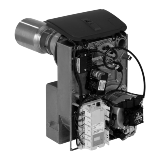
Component overview Component overview Fig. 15 Service switch (for burner adjustment) Suction line or return line (differs subject to manu- Hood adaptor facturer) Quick-action fastener Solenoid valve, stage 2 Electronic ignition unit Solenoid valve, stage 1 Servomotor Flame monitor Burner control unit Return line or suction line (differs subject to manu- facturer) - Page 22 Component overview Component overview (cont.) Fig. 16 Reset button Blast tube connection Oil line Flame tube Oil pump Mixing device Fan motor Oil burner nozzle Fan casing Ignition electrodes Impeller Ignition cable Inlet air silencer Flange Air regulating valve Adaptor pipe...
-
Page 23: Connection And Wiring Dia
Connection and wiring diagram Connection and wiring diagram Fig. 17 Burner control unit (see chapter "Program Colour coding to DIN IEC 60757 sequence during commissioning") Black Fault indicator Black wire with imprint Reset button Brown Burner motor Blue Service switch (burner stage 2) Flame monitor GN/YE Green/yellow... -
Page 24: Parts Lists Parts Lists
Parts lists Parts lists Ordering parts The following information is required: Standard parts are available from your local supplier. ■ Serial no. (see type plate ■ Assembly (from this parts list) ■ Position number of the individual part within the assembly (from this parts list) Overview of assemblies Fig. -
Page 25: Burner Casing Assembly
Parts lists Casing assembly (cont.) 0002 0003 0003 0001 Fig. 19 Burner casing assembly 0001 Burner casing 0007 Seal ring, burner flange 0002 Adaptor pipe 0008 Burner hood adaptor 0003 Fixing screw M 8 x 8 0009 Rocker switch 0004 Sound insulation set 0010 Cover flap 0005 Flame tube 0011 Illuminated rocker switch... -
Page 26: Burner Cover Assembly, 67.6 Kw
Parts lists Burner casing assembly (cont.) 0010 0011 0009 0008 0005 0002 0003 0003 0001 0007 0002 0003 0004 0006 0008 0010 0004 0006 Fig. 20 Burner cover assembly, 67.6 kW 0001 Electronic ignition unit 0010 Oil hose, flow 0002 Actuator 0011 Threaded connector 0003 Burner control unit 0012 Seal rings, Cu R... -
Page 27: Burner Cover Assembly, 85.8 And 107.3 Kw
Parts lists Burner cover assembly, 67.6 kW (cont.) 0008 0006 0001 0002 0003 0004 0007 0007 0016 0014 0016 0015 0005 0017 0016 0013 0018 0018 0012 0011 0012 0010 0009 Fig. 21 Burner cover assembly, 85.8 and 107.3 kW 0001 Electronic ignition unit 0005 Plug-in coupler 0002 Actuator... -
Page 28: Blast Tube Connection Assembly
Parts lists Burner cover assembly, 85.8 and 107.3 kW (cont.) 0012 Seal rings, Cu R 0016 Coil ¼ 0013 Pivoting angle fitting 0017 Oil pump 0014 Connecting cable, oil pump stage 2 0018 Spare parts set, oil pump 0015 Connecting cable, oil pump stage 1 0008 0006 0001... - Page 29 Parts lists Blast tube connection assembly (cont.) 0005 Oil nozzle (wearing part) 0009 Compression spring 0006 Mixing system 0010 Nozzle cover 0007 Blast tube connection 0011 Anti-twist lock, blast tube connection 0008 Cable entry 0006 0004 0004 0003 0005 0003 0007 0009 0009...
-
Page 30: Miscellaneous
Parts lists Miscellaneous 0001 Burner installation instructions 0003 Service instructions 0002 Installation instructions 0004 Small parts 0001 0002 0003 0004 Fig. 24... -
Page 31: Report
Report Report Settings and test values Commissioning Maintenance/service (Set values, see chapter "Standard values for burner adjustment", page ) Oil pressure Stage 1 actual ■ Stage 2 actual ■ Vacuum actual after maintenance bar Soot value Stage 1 actual ■ after maintenance Stage 2 actual... -
Page 32: Specification
Specification Specification Rated boiler heating output = 50/30 67.6 85.8 107.3 ° = 80/60 ° Rated burner heat input 45.9/65.6 58.3/83.3 72.9/104.2 stage 1/2 Burner type VHG III-1 VHG III-2 VHG III-3 DIN registration no. Applied for Voltage Frequency Power consumption Stage 1: 585 Stage 2: 616 Motor speed... -
Page 33: Standard Values For Burner
Standard values for burner adjustment Standard values for burner adjustment Rated heating output of the boiler = 50/30 67.6 85.8 107.3 ° = 80/60 ° Oil burner nozzle Make: Danfoss Type ° ° ° 1.35 1.75 Oil pressure approx. Stage 1 bar min. -
Page 34: Appendix Information On Fuel Oil
The use of combustion improvers that leave res- idues is not permissible. Biofuels Biofuels are made from vegetable oil, e.g. sunflower or rapeseed oil. Please note Biofuels can lead to damage to Viessmann oil burners. Their use is not permissible. -
Page 35: Keyword Index
Keyword index Keyword index Flash code..............18 Additives for fuel oil............ 34 Flowchart, burner faults..........16 Air damper position............8 Fuel oil Air damper servomotor, checking the settings..... 8 – Additives..............34 – Quality..............34 Biofuels..............34 Burner cleaning............10 Ignition air setting............8 Burner control unit Ignition electrodes, checking and adjusting.... - Page 36 Applicability Serial No.: 7502108 7502109 7369082 Viessmann Werke GmbH & Co. KG Viessmann Limited D-35107 Allendorf Hortonwood 30, Telford Telephone: +49 6452 70-0 Shropshire, TF1 7YP, GB Fax: +49 6452 70-2780 Telephone: +44 1952 675000 www.viessmann.com Fax: +44 1952 675040...
Need help?
Do you have a question about the Vitoflame 300 VHG III and is the answer not in the manual?
Questions and answers