Table of Contents
Advertisement
Quick Links
Advertisement
Table of Contents

Subscribe to Our Youtube Channel
Related Manuals for Zmotion ZMC004WEA


Summary of Contents for Zmotion ZMC004WEA
- Page 2 This manual is copyrighted by Shenzhen Technology Co., Ltd., without the written permission of the Zmotion Technology, no person shall reproduce, translate and copy any content in this manual. The above-mentioned actions will constitute an infringement of the copyright of the company's manual, and Zmotion will investigate legal responsibility according to law.
- Page 3 ⚫ Zmotion will not take any legal responsibility for personal safety accidents and property losses caused by failure to comply with the contents of this manual or illegal operation of products. Safety Level Definition According to the level, it can be divided into "...
- Page 4 ◆ Improper installation of the controller may result in misoperation, failure and fire. Wiring ◆ The specifications and installation methods of the external wiring of the equipment shall comply with the requirements of local power distribution regulations. ◆ When wiring, all external power supplies used by the system should be disconnected before operation.
-
Page 5: Table Of Contents
ZMC004WEA Motion Controller User Manual V1.5 Content Chapter I Production Information..................3 1.1. Product Information ..................3 1.2. Function Features ....................3 1.3. System Frame ....................4 1.4. Hardware Installment ..................4 Chapter II Product Specification ..................7 2.1. Basic Specification .................... 7 2.2. - Page 6 ZMC004WEA Motion Controller User Manual V1.5 3.5.2. Basic Usage Method ................26 3.6. AD/DA Analog Input/Output ................27 3.6.1. Analog Input / Output Specification & Wiring ........27 3.6.2. Basic Usage Method ................29 3.7. EtherCAT Bus Interface / Ethernet ..............29 Chapter IV Expansion Module ...................
-
Page 7: Chapter I Production Information
4 axes, but 6 axes can be expanded to achieve some simple trajectory control requirements, such as, linear interpolation, circular interpolation, helical interpolation, etc. ZMC004WEA economical multi-axis motion controllers can be applied in pulse applications within 6 axes, electronic semiconductor equipment (testing equipment, assembly equipment, locking equipment, soldering machine), dispensing equipment, assembly line, etc. -
Page 8: System Frame
◆ A variety of program encryption methods to protect the intellectual property rights of customers. ◆ Support power failure detection and power failure storage. 1.3. System Frame 1.4. Hardware Installment The ZMC004WEA motion controller is installed horizontally with screws, and each controller should be fastened with 4 screws. - Page 9 ZMC004WEA Motion Controller User Manual V1.5 → Unit: mm → Mounting Hole Diameter 4.5mm Non-professionals are strictly prohibited to operate. Specifically, ⚫ professionals who had been trained related electrical equipment, or who master electrical knowledge. ⚫ Please be sure to read the product instruction manual and safety precautions carefully before installation.
- Page 10 ZMC004WEA Motion Controller User Manual V1.5 places where the ambient humidity exceeds the range of 10%- 95% (non-condensing) places with corrosive gases and flammable gases places with many conductive powders such as dust and iron powder, oil mist, salt, and organic solvents...
-
Page 11: Chapter Ii Product Specification
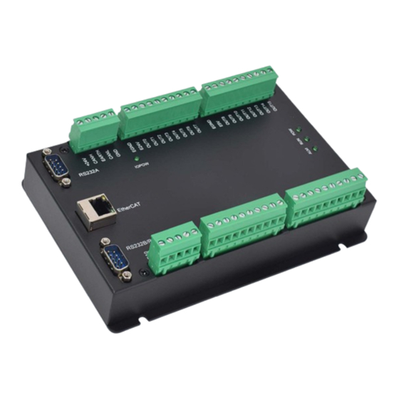
ZMC004WEA Motion Controller User Manual V1.5 Chapter II Product Specification 2.1. Basic Specification Item Description Model ZMC004WEA ZMC004BEA Basic Axes Max Extended Axes Array space 16000 2400 Flash space 8MByte 2MByte Type of Basic Axes EtherCAT/local pulse axes/encoder axes Digital IO There are 16 inputs and 16 outputs. -
Page 12: Interface Definition
ZMC004WEA Motion Controller User Manual V1.5 3 axes, point to point, electronic cam, linear, circular, continuous ZMC003WEA trajectory motion. 4 axes, point to point, electronic cam, linear, circular, continuous ZMC004BEA trajectory motion. 3 axes, point to point, electronic cam, linear, circular, continuous ZMC003BEA trajectory motion. -
Page 13: Work Environment
ZMC004WEA Motion Controller User Manual V1.5 → Interface Description Mark Interface Number Description Power state: it lights when power is conducted. The led that indicates the current state. Run state: it lights when runs normally Error state: it lights when runs incorrectly... - Page 14 ZMC004WEA Motion Controller User Manual V1.5 Storage Temperature -40℃~80℃ (not frozen) Storage Humidity Below 90%RH (no frost) Frequency 5-150Hz Displacement 3.5mm(directly install)(<9Hz) vibration Acceleration 1g(directly install)(>9Hz) Direction 3 axial direction Shock (collide) 15g, 11ms, half sinusoid, 3 axial direction Degree of Protection...
-
Page 15: Chapter Iii Wiring, Communication Configuration
ZMC004WEA Motion Controller User Manual V1.5 Chapter Wiring, Communication Configuration 3.1. Power Input, CAN Communication Interface The power supply input adopts a 5Pin (there are all 5 terminals) screw-type pluggable wiring terminal, and the interval (means the gap distance between two ports) should be 5.08mm. -
Page 16: Power Specification
ZMC004WEA Motion Controller User Manual V1.5 3.1.1. Power Specification → Specification Item Main Power IO Power Voltage DC24V(-5%~5%) DC24V(-5%~5%) The current to open ≤0.5A ≤0.3A The current to work ≤0.4A ≤0.2A Anti-reverse connection Valid Valid Overcurrent Protection Valid Valid 3.1.2. CAN Communication Specification & Wiring CAN interface of the controller uses standard CAN communication protocol, there are mainly 3 terminals, CANL, CANH and public end. - Page 17 ZMC004WEA Motion Controller User Manual V1.5 → Wiring Notes: As above, the daisy chain topology is used for wiring, so the star topology cannot be ⚫ used. When the use environment is ideal and there are few nodes, the branch structure can also be considered.
-
Page 18: Basic Usage Method
ZMC004WEA Motion Controller User Manual V1.5 Twisted pair shielded wire, and shielded cable grounded. 3.1.3. Basic Usage Method (1) Please follow the above wiring instructions for correct wiring. (2) After power on, please use ETHERNET, RS232 or RS485 to connect to ZDevelop. -
Page 19: Rs232A Serial Port
ZMC004WEA Motion Controller User Manual V1.5 3.2. RS232A Serial Port RS232A is in one standard DB9 male socket and supports MODBUS_RTU protocol and custom communication. → Interface Definition: Terminal Name Type Function 1, 4, 6, Spare Reserved 7, 8 232A-RXD... -
Page 20: Basic Usage Method
ZMC004WEA Motion Controller User Manual V1.5 → Wiring Reference: → Wiring Notes: The wiring of RS232A is as above, it needs to cross-wiring for sending and receiving ⚫ signals, and it is recommended to use a double-female head cross line when connecting to a computer. -
Page 21: Rs232B/Rs485 Serial Port
ZMC004WEA Motion Controller User Manual V1.5 (2) After powered on, please use any one interface among the three interfaces ETHERNET, RS232 (there is default parameter, which can be connected directly) and RS485 (there is default parameter, which can be connected directly, but for hardware, adapter head is needed) to connect to ZDevelop. -
Page 22: Rs232B/Rs485 Serial Port Communication Specification & Wiring
ZMC004WEA Motion Controller User Manual V1.5 protocol and custom communication. → Interface Definition: Terminal Name Type Function 1, 6, 8, 9 Spare Reserved RS232B (port 1) receive 232B-RXD Input signal 232B-TXD Output RS232B (port 1) send signal 485A/+ Input/output RS485 (port 2) signal A/+... - Page 23 ZMC004WEA Motion Controller User Manual V1.5 → Wiring Notes: ⚫ The wiring of RS232B (port 1) is as above, the sending and receiving signals need to be cross-connected, and it is recommended to use a double-female cross line when connecting to a computer.
-
Page 24: Basic Usage
ZMC004WEA Motion Controller User Manual V1.5 3.3.2. Basic Usage (1) Please follow the above wiring instructions for correct wiring. (2) After powered on, please use any one interface among the three interfaces ETHERNET, RS232 (there is default parameter, which can be connected directly) and RS485 (there is default parameter, which can be connected directly, but for hardware, adapter head is needed) to connect to ZDevelop. -
Page 25: In Digital Input & Latch Port & Single-Ended Encoder
ZMC004WEA Motion Controller User Manual V1.5 3.4. IN Digital Input & Latch Port & Single-ended Encoder The digital input adopts 2 groups of 10Pin (there are 3 groups of 10 terminals) screw- type pluggable terminals, and the gap distance between terminals should be 5.08mm. In addition, the latch function is integrated in digital input signals. -
Page 26: Digital Input Specification & Wiring
ZMC004WEA Motion Controller User Manual V1.5 EGND Input 8 Input 9 IN10 Input 10 NPN type, low- IN11 speed input Input 11 IN12 Input 12 IN13 Input 13 IN14 NPN type, high- Input 14 speed input IN15 Input 15 Note: IN 0 and IN 1 both support latch function, IN0 corresponds to latch A, IN1 ... -
Page 27: Basic Usage Method
ZMC004WEA Motion Controller User Manual V1.5 → Wiring Note: The wiring principle of high-speed digital input IN (14-15) and low-speed digital input ⚫ IN (0-13) is shown in the figure above. The external signal source can be an optocoupler, a key switch or a sensor, etc., all can be connected as long as the requirements on output of electric level can be achieved. -
Page 28: Out Digital Output, Single-Ended Pulse
ZMC004WEA Motion Controller User Manual V1.5 (4) Latch function can be set and triggered through “REGIST” instruction, in software, use REG_INPUTS to configure. Please refer to “ZBasic” for details. 3.5. OUT Digital Output, Single-ended Pulse The digital output adopts 2 sets of screw-type pluggable terminals with a spacing of 5.08mm, and the PWM function is integrated in digital output signal. -
Page 29: Digital Output Specification & Wiring
ZMC004WEA Motion Controller User Manual V1.5 OUT15 Output 15 PUL0 Note: The E5V power output port is used for PWM or common anode wiring of single- ended axis. It is not recommended for other purposes due to lower power. -
Page 30: Basic Usage Method
ZMC004WEA Motion Controller User Manual V1.5 → Wiring Note: The wiring principle of high-speed digital output OUT (0-7) and low-speed digital ⚫ output OUT (8-15) is shown in the figure above. The external signal receiving end can be an optocoupler or a relay or solenoid valve, all can be connected as long as the input current does not exceed 300mA. -
Page 31: Ad/Da Analog Input/Output
ZMC004WEA Motion Controller User Manual V1.5 3.6. AD/DA Analog Input/Output The analog port adopts a set of 5Pin screw-type pluggable terminals with a spacing of 5.08mm. → Terminal Definition Terminal Name Type Function Analog output terminal: AOUT(0) Output Analog output terminal: AOUT(1) - Page 32 ZMC004WEA Motion Controller User Manual V1.5 Data refresh ratio 1KHz 1KHz Voltage input impedance / >10KΩ (voltage output 300KΩ (voltage input output load load) impedance) → Wiring Reference → Wiring Note: ⚫ The analog input/output wiring method is as shown in the figure above, and the external load signal range must match with this signal range.
-
Page 33: Basic Usage Method
“ZDevelop/View/AD/DA”. Please refer to “ZBasic” for details. 3.7. EtherCAT Bus Interface / Ethernet ZMC004WEA motion controller has a 100M EtherCAT communication interface, and it supports EtherCAT protocol. In addition, EtherCAT driver or EtherCAT expansion module can be connected. Also, it can be ethernet to communicate with host computer, and supports MODBUS_TCP protocol and custom communication. - Page 34 ZMC004WEA Motion Controller User Manual V1.5 → Specification Item Specification Communication protocol EtherCAT protocol Valid service CoE(PDO, SDO), FoE IO adopts input and output synchronization / DC- Synchronization method distributed clock Physical level 100BASE-TX Duplex mode Full duplex Topology linear topology...
- Page 35 ZMC004WEA Motion Controller User Manual V1.5 The controller can also be connected to the interchanger through an Ethernet cable, and then use interchanger to connect to other devices, then multi-point connection can be achieved. The schematic diagram is as follows: →...
- Page 36 ZMC004WEA Motion Controller User Manual V1.5 Item Specification Cable type Flexible crossover cable, Category 5e traverse twisted pair Line pairs Isolation cross skeleton Connector Crystal head with iron shell Cable material Cable length Less than 100m Use RJ45 network cable connection method: When installing, hold the crystal head that is with the cable and insert it into the RJ45 ⚫...
-
Page 37: Chapter Iv Expansion Module
ZMC004WEA Motion Controller User Manual V1.5 Chapter IV Expansion Module The controller can expand digital IO, analog IO, pulse axis and other resources through CAN bus (ZIO series expansion modules). For details, please refer to "ZIO Expansion Card Hardware Manual". Also, through EtherCAT bus (EIO series expansion cards) expansion of these resources also can be achieved, please refer to each EIO hardware manual for details. - Page 38 ZMC004WEA Motion Controller User Manual V1.5 → Wiring Note: ZMC004WEA controller uses the dual power, and ZIO expansion module uses dual- power. When using, main power supply of expansion module and main power supply of controller can share one power. When they use different power supplies, controller power EGND needs to connect to expansion module power GND, otherwise CAN may be burnt out.
-
Page 39: Can Bus Expansion Resource Mapping
ZMC004WEA Motion Controller User Manual V1.5 4.1.2. CAN Bus Expansion Resource Mapping The ZCAN expansion module generally has an 8-bit DIP switch, dial ON to take effect, and the meaning of the DIP is as follows: 1-4: they are used for ZCAN expansion module IO address mapping, the corresponding value is 0-15. - Page 40 ZMC004WEA Motion Controller User Manual V1.5 command. There are also four speed parameters that can be selected. The communication speed must be consistent with the communication speed of the expansion module that corresponds to the combination value, then they can communicate with each other.
- Page 41 ZMC004WEA Motion Controller User Manual V1.5 The initial IO mapping number of the analog AD starts from 8 and increases in multiples of 8. The initial IO mapping number of the analog DA starts from 4 and increases in multiples of 4. The allocation of digital IO numbers corresponding to different dial code...
- Page 42 ZMC004WEA Motion Controller User Manual V1.5 be selected to expand two pulse axes. These two pulse axes need to be mapped and bound with the axis No., then access. Extended axes need to perform axis mapping operations, using the AXIS_ADDRESS command to map, and the mapping rules are as follows: AXIS_ADDRESS(axis No.)=(32*0)+ID...
-
Page 43: Ethercat Bus Expansion
ZMC004WEA Motion Controller User Manual V1.5 ALMRM indicator light is on, please check whether the wiring, resistor and dial setting are correct, and whether the CANIO_ADDRESS command of the controller is set as the master end (32), and whether the CAN communication speed is consistent. -
Page 44: Ethercat Bus Expansion Resource Mapping
ZMC004WEA Motion Controller User Manual V1.5 Involved number concepts in above figure are as follows: the bus-related command parameters will use the following numbers: Slot number (slot): The slot number refers to the number of the bus interface on the controller, and the slot number of the EtherCAT bus is 0. - Page 45 ZMC004WEA Motion Controller User Manual V1.5 only through the IO number. The IO number of the EtherCAT bus expansion module is set through the bus command NODE_IO, and the input and output are configured at the same time. When IO mapping, first check the maximum IO number of the controller itself (including the external IO interface and the interface in the pulse axis), and then use the command to set.
- Page 46 ZMC004WEA Motion Controller User Manual V1.5 Example: AXIS_ADDRESS(0)=(0<<16)+0+1 'the first drive on the EtherCAT bus, drive number 0, bound as axis 0 AXIS_ADDRESS(1)=(0<<16)+1+1 'the second drive on the EtherCAT bus, drive number 1, bound as axis 1 If the first node is EIO16084, and EIO16084 is connected to drive, then driver 0 here...
-
Page 47: Chapter V Program & Applications
5.1. ZDevelop Software Usage ZDevelop is a PC-side program development, debugging and diagnostic software for the ZMoiton series motion controllers of Zmotion Technology. Through it, users can easily edit and configure the controller program, quickly develop applications, diagnose system operating parameters in real time, and watch the motion controller. The running program is debugged in real time and supports Chinese and English bilingual environments. - Page 48 ZMC004WEA Motion Controller User Manual V1.5 Click “File” – “New File”, select file type to build, here select Basic, click “OK”. Double click “AutoRun”, enter task number 0.
- Page 49 ZMC004WEA Motion Controller User Manual V1.5 Edit program program editing window, click “save”, built basic file will be saved under “zpj.” project automatically. “Save all” means all files under this project will be saved. Click “controller – connect”, if no...
- Page 50 ZMC004WEA Motion Controller User Manual V1.5 parameters port address, then click “connect”. Click “Ram/Rom” – “download RAM download ROM”, if it is successful, there is print indication, the same time, program downloaded into controller runs automatically. RAM: it will not...
- Page 51 ZMC004WEA Motion Controller User Manual V1.5 Click “Debug” – “Start/Stop Debug” to call “Task” “Watch” window, because it was downloaded before, here select “Attach the current”. Click “View” – “Scope” to open oscilloscope. Note: ⚫ When opening an project, choose to open the zpj file of the project. If only the Bas file is opened, the program cannot be downloaded to the controller.
-
Page 52: Pc Upper-Computer Program Application
Mac, Android, and wince, and provides dll libraries in various environments such as vc, c#, vb.net, and labview, as shown in the figure below. PC software programming refers to "ZMotion PC Function Library Programming Manual". The program developed using the PC software cannot be downloaded to the controller, and it is connected to the controller through the dll dynamic library. - Page 53 ZMC004WEA Motion Controller User Manual V1.5 Select development language “Visual C++” and the select program type “MFC application type”. Select “Based on basic box”, click “next” or “finish” Find function library provided manufacturer. Routine below (64-bit library) Copy all DLL related library files under the above path to the newly created project.
- Page 54 ZMC004WEA Motion Controller User Manual V1.5 zmotion.lib Item". Related header 2) Add static files: libraries and zauxdll2.h, related zmotion.h header files in sequence in the pop-up window. Declare relevant header files and define controller connection handle, so far the project is...
-
Page 55: Chapter Vi Run And Maintain
ZMC004WEA Motion Controller User Manual V1.5 Chapter VI Run and Maintain The correct operation and maintenance of the device can not only guarantee and extend the life cycle of the equipment itself, but also take technical management measures according to the pre-specified plan or the corresponding technical conditions to prevent equipment performance degradation or reduce the probability of equipment failure. -
Page 56: Common Problems
ZMC004WEA Motion Controller User Manual V1.5 Should be within the range of Whether the device is subjected to vibration resistance vibration or shock impact resistance Keep good ventilation and Is the heat dissipation good heat dissipation The mounting screws should... - Page 57 ZMC004WEA Motion Controller User Manual V1.5 invalid. and whether the "input" view can watch the signal change of the limit sensor. Check whether the mapping of the limit switch is correct. Check whether the limit sensor is connected to the common terminal of the controller.
- Page 58 ZMC004WEA Motion Controller User Manual V1.5 Check master-slave configuration, communication speed configuration, etc. Check the DIP switch to see if there are multiple expansion modules with the same ID. Use twisted-pair cables, ground the shielding layer, and use dual power supplies for severe interference...
Need help?
Do you have a question about the ZMC004WEA and is the answer not in the manual?
Questions and answers