Table of Contents
Advertisement
Quick Links
Welcome to Follett
Follett equipment enjoys a well-deserved reputation for excellent performance, long-term reliability and outstanding
after-the-sale support. To ensure that this equipment delivers that same degree of service, review this guide carefully
before you begin your installation.
Should you have need technical help, please call our Technical Service group at (877) 612-5086 or (610) 252-7301.
Please have your model number, serial number and complete and detailed explanation of the problem when
contacting Technical Service.
Getting Started
After uncrating and removing all packing material. Inspect the equipment for concealed shipping damage. All freight
is to be inspected upon delivery. If visible signs of damage exist, please refuse delivery or sign your delivery receipt
"damaged." Follett Customer Service must be notified within 48 hours. Wherever possible, please include detailed
photos of the damage with the original packaging so that we may start the freight claim process.
801 Church Lane • Easton, PA 18040, USA
Toll free (877) 612-5086 • +1 (610) 252-7301
www.follettice.com
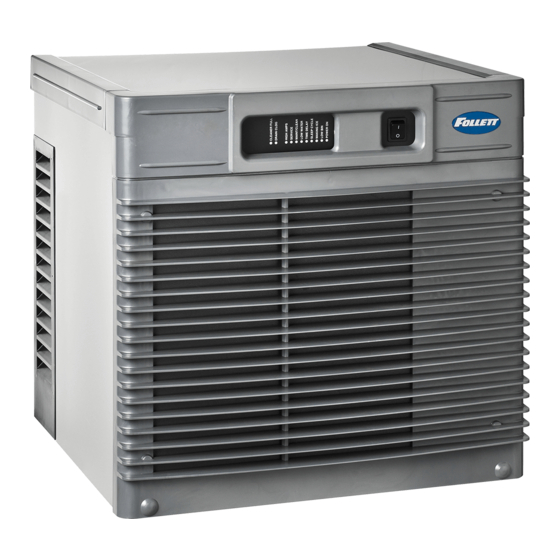
MC_425A/W, MF_425A/W, _P425A/W
Ice Machines - 230 V 50 Hz, 220 V 60 Hz
Installation, Operation and Service Manual
Please visit https://www.follettice.com/technicaldocuments
MCC425A/W_S
MCE425A/W_S
ER425A/W
After serial number L89952
for the Operation and Service manual for your unit.
MCC425A/W_T
MCE425A/W_T
MFC425A/W_T
MFE425A/W_T
CP425A/W
EP425A/W
Installation and Service Videos:
www.follettice.com/servicevideolibrary
01234640R07
Advertisement
Table of Contents

Subscribe to Our Youtube Channel
Related Manuals for Follett MC-425A/W


Summary of Contents for Follett MC-425A/W
- Page 1 If visible signs of damage exist, please refuse delivery or sign your delivery receipt "damaged." Follett Customer Service must be notified within 48 hours. Wherever possible, please include detailed photos of the damage with the original packaging so that we may start the freight claim process.
-
Page 2: Table Of Contents
Welcome to Follett........ - Page 3 § This appliance must not be cleaned by a water jet. § User maintence should not be done by children. § Follett recommends a Follett water filter system be installed in the ice machine inlet water line (standard capacity #00130229, high capacity #00978957, carbonless high capacity #01050442).
- Page 4 Check your paperwork to determine which model you have. Follett model numbers are designed to provide information about the type and capacity of Follett equipment. Following is an explanation of the different model numbers in the 425 series. MCE425ABT Configuration T –...
-
Page 5: Specifications
§ Separate drains for ice machine and condenser. To prevent back flow, do NOT connect drains. § Follett recommends a Follett water filter system be installed in the ice machine inlet water line (standard capacity #00130229, high capacity #00978957, carbonless high capacity #01050442). - Page 6 Technical specifications Refrigeration pressure data § Water regulating valve is factory set at 300 ±10 PSIG (2068.4 ± 69 kPA) head pressure. § Readings within 10% of table values should be considered normal. Compressor data Air-cooled Ambient air temperature 60 F/15.6 C 70 F/21.1 C 80 F/26.7 C 90 F/32.2 C...
-
Page 7: Dimensions And Clearances
Dimensions and clearances § Entire front of ice machine must be clear of obstructions/connections to allow removal. § 12" (30.5 cm) clearance above ice machine for service. § 6" (15.3 cm) minimum clearance between exhaust side of ice machine and any adjacent equipment. §... -
Page 8: Cleaning
Periodic cleaning of Follett’s ice machine system is required to ensure peak performance and delivery of clean, sanitary ice. The recommended cleaning procedures that follow should be performed at least as frequently as recommended and more often if environmental conditions dictate. - Page 9 § Do not use solvents, abrasive cleaners, metal scrapers or sharp objects to clean any part of the dispenser. SafeCLEAN Plus Solution: Follow the directions on the SafeCLEAN Plus packaging to mix 1 gal. (3.8 L) of Follett SafeCLEAN Plus solution. Use 100 F (38 C) water.
-
Page 10: Service
Service Ice machine Operation (all models) Follett’s ice machine consists of four distinct functional systems: § Harvesting system § Refrigeration system § Water system § Electrical control system These four systems work together to accomplish the production and harvesting of ice. A problem in any one of these systems will result in improper operation of the entire ice production cycle. -
Page 11: Water System
Water system The water level in the evaporator is controlled by a fill solenoid (Fig 1) and level detecting sensors. Water sensing rods (Fig. 2) extend down into the reservoir at the end of the evaporator assembly. The system works via electrical conductivity as follows: One of the longest probes is a common. -
Page 12: Electrical System
Electrical system ATTENTION! To prevent circuit breaker overload, wait 15 minutes before restarting this unit. This allows the compressor to equalize and the evaporator to thaw. Normal control board operation The PC board indicator lights provide all the information necessary to determine the machine's status. Green indicator lights generally represent “go”... - Page 13 A soft error can either be automatically reset should the condition rectify, or if power is cycled. Should an error occur, consult the troubleshooting guide in this manual or a Follett service technician.
-
Page 14: Electrical Control System Schematic - 230 V 50 Hz
Electrical control system schematic - 230 V 50 Hz BLACK #26 WHITE #25 L2/N GRN-YEL #24 BLACK #23 BLACK #23 DISP BLACK #51 CONTACT POWER ICE AUX WATER AUX CLOSURE LOW BIN BLACK #01 MAKING ICE SLEEP CYCLE HI PRS TIME DELAY LOW WATER MAINTENANCE... -
Page 15: Electrical Control System Schematic - 220 V 60 Hz
PRESS Electrical control system operation The wiring diagrams that follow illustrate the circuitry of these Follett ice machines used with ice dispensers. Both normal operation of the ice machine (Stages 1–6) and non-normal diagnostic sequences showing torque-out (Stages 7–10) for use in troubleshooting ice machine problems are shown. - Page 16 Normal operation – Stage 1 - 230V 50 Hz Power is supplied to L1 of the control board, the POWER LED light begins flashing. The ice level bin thermostat in the dispenser is closed and calling for ice, supplying contact closure to the control board. The LOW BIN LED will be on.
- Page 17 Normal operation – Stage 2 When continuity is seen between B and C, the water valve de-energizes, the AUGER output (P4) comes on along with the MAKING ICE LED. The auger gearmotor’s start windings are energized through a current style start relay that is pulled in by the initial high current draw of the gearmotor.
- Page 18 Normal operation – Stage 4 One second (1 s) after the fan comes on, the COMPRESSOR output comes on. The compressor circuit uses both run and start capacitors along with a potential start relay. The start capacitor in energized through the normally closed contacts of the start relay.
- Page 19 Normal operation – Stage 6 Once the bin thermostat control opens, the LOW BIN LED goes out. The compressor and gear motor outputs turn off, the MAKING ICE LED goes out and the TIME DELAY LED comes on. . T.O.L. High Pressure Switch...
- Page 20 Normal operation – Stage 8 When the dwell time of 20 minutes has expired, the TIME DELAY LED goes off. If 5 seconds of ice has been dispensed and the SLEEP CYCLE LED is off, the ice machine will go through the normal start-up sequence when the bin level control signals the control board for ice.
- Page 21 Self-flushing At the completion of the 20 minute time delay, the machine checks for a cumulative one hour of ice making time since the last off-cycle flush. If the cumulative ice making time exceeds one hour, the machine will energize the drain valve P19 for 60 seconds to drain the evaporator.
- Page 22 High gearmotor amps – Stage 2 If the restart is successful the board will continue to monitor the current draw on P4 for 60 minutes looking for a second high amps (above 1.8A) or no current draw (0A) occurrence. If the ice machine runs without problems for 60 minutes and no additional torque errors occur, the ice machine will continue normal operation.
- Page 23 Loss of water During operation, the water level cycles between the normal low (D) and normal high (C) water probes - the fill valve (P21) cycling on and off. If continuity is not detected between the common probe (B) and normal low (D) within 10 seconds, the LOW WATER and TIME DELAY LEDs will come on and the machine will shut down for the one hour time delay period.
- Page 24 High refrigerant pressure Should the refrigeration pressure rise above 425 PSI (2930.3 kPA), the high pressure switch contacts will open. The board sees the open circuit and the HIGH PRESSURE and TIME DELAY LEDs will come on, the machine shuts down. After the one hour time delay, the machine will attempt to restart. If the pressure has fallen below the reset point of 295 PSI (2034.0 kPA) and the board see the contacts closed, the machine will resume normal operation.
-
Page 25: Refrigeration System (All Models)
Refrigeration system (all models) All service on refrigeration systems must be performed in accordance with all federal, state and local laws. It is the responsibility of the technician to ensure that these requirements are met. Recharging ice machine to other than factory specifications will void the warranty. - Page 26 R404A Refrigerant replacement requirements 1. Non-contaminated refrigerant removed from any Follett refrigeration system can be recycled and returned to the same system after completing repairs. Recycled refrigerant must be stored in a clean, approved storage container. If additional refrigerant is required, virgin or reclaimed refrigerant that meets ARI standard 700-88 must be used.
- Page 27 Evacuation Evacuate the system to a level of 500 microns. When the 500 micron level is reached, close valves and both manifold and shut down the vacuum pump. Allow the system to sit for approximately 20 minutes. During this period the system pressure should not rise.
- Page 28 Evaporator disassembly Note: The upper bearing, lower bearing and auger assemblies must be replaced as assemblies. The bottom and top bearing assemblies cannot be field assembled to factory specifications. 1. Press CLEAN switch. Fig. 3 2. Wait for LOW WATER light to illuminate. 3.
- Page 29 6. Lower bottom bearing assembly into Fig. 5 evaporator mounting base. 7. While maintaining firm downward pressure on bottom bearing assembly, tighten hex head bolt with a 5/16 wrench. 8. Position evaporator over lower bearing assembly and align grooves with pins in bearing assembly.
-
Page 30: Replacement Parts
Replacement parts Replacement ice machine ordering matrix Dispenser models Replacement ice machine model Dispensers with top mounted ice machines C/E110CT425A C/EP425A C/E110CT425W C/EP425W Dispensers with RIDE ice machines All C/EU150/VU155 series with air-cooled ice machines (220 V/230 V) MC_425AVS All C/EU150/VU155 series with water-cooled ice machines (220 V/230 V) MC_425WVS All C/EVU300 series with air-cooled ice machines (220 V/230 V) MC_425AVS... -
Page 31: Air-Cooled Skins Assembly (Mce425A_S)
Air-cooled skins assembly (MCE425A_S) Reference # Description Part # Gasket, duct 502781 Duct (including gasket) 01068188 Front panel 01068204 Spacer, base 01068220 Panel, right side 01068238 Panel, left side and rear (1 piece) 01068246 Bushing 01026152 Panel, top 01068253 Tube, drain 01016948 Fitting, water 01065275... -
Page 32: Water-Cooled Skins Assembly (Mce425W_S)
Water-cooled skins assembly (MCE425W_S) Reference # Description Part # Fitting, condenser 00195966 Fitting, water 01065375 Fitting, drain 00109728 Panel, front 01068261 Spacer, base 01068220 Panel, right side 01068238 Tube, drain 01016948 Panel, left side and rear (1 piece) 01068246 Bushing 01026152 Panel, top 01068253... -
Page 33: Louvered Docking Station (Mce425A/W_T)
Louvered docking station (MCE425A/W_T) Reference # Description Part # Louver, front 01006154 Cover, front 01068279 Tube, drain 01055185 Lovered docking station 01068287 Not shown Power, cord 01111673 MC_425A/W, MM_425A/W, MF_425A/W, _P425A/W Ice Machines... -
Page 34: Evaporator
Evaporator FOOD SERVICE FLAKER COMPONENTS HEALTHCARE MicroChewblet FLAKER MC_425A/W, MM_425A/W, MF_425A/W, _P425A/W Ice Machines... - Page 35 Evaporator Reference # Description Part # Coupling, vee band, includes nut 502735 Bearing assembly, top 502736 Loop, ice compression, beveled (see below for Flaker-specific components) 502110 Auger (see below for Flaker-specific components) 502737 Evaporator (includes insulation jacket, 502740) 01064658 O ring, bearing housing 500496 Bearing assembly, bottom (includes O rings and condensate shield) 502738...
- Page 36 Shuttle Assembly Standard on MCE425AHS, MCE425AVS, MME425ABS, MCE425AJS, MCE425ABS, MME425AJS Models only MC_425A/W, MM_425A/W, MF_425A/W, _P425A/W Ice Machines...
- Page 37 Evaporator Reference # Description Part # Cable, bin signal, shuttle 01374222 Cartridge assembly, shuttle spring 01118033 Switch, shuttle 01006261 Switch, spring and cartridge assembly 01374230 Shuttle nozzle assembly 01374214 Not Shown Complete shuttle assembly 01374404 MC_425A/W, MM_425A/W, MF_425A/W, _P425A/W Ice Machines...
-
Page 38: Air-Cooled Ice Machines - 230 V 50 Hz
Air-cooled ice machines - 230 V 50 Hz MC_425A/W, MM_425A/W, MF_425A/W, _P425A/W Ice Machines... - Page 39 Air-cooled ice machines - 230 V 50 Hz Reference # Description Part # Drier 502724 Condenser coil, A/C 01067461 Reservoir mounting bracket (after serial number L89952) 01375609 Reservoir (includes lid, gasket, fasteners, clean and vent tubing, cleaning cup) 01230630 Bracket, electrical box 01068170 Evaporator (see page 34 and 35 for complete breakdown) —...
-
Page 40: Air-Cooled Ice Machines - 220 V 60 Hz
Air-cooled ice machines - 220 V 60 Hz MC_425A/W, MM_425A/W, MF_425A/W, _P425A/W Ice Machines... - Page 41 Air-cooled ice machines - 220 V 60 Hz Reference # Description Part # Drier 502724 Condenser coil, A/C 01067461 Reservoir mounting bracket (after serial number L89952) 01375609 Reservoir (includes lid, gasket, fasteners, clean and vent tubing, cleaning cup) 01230630 Bracket, electrical box 01068170 Evaporator (see page 34 and 35 for complete breakdown) —...
-
Page 42: Water-Cooled Ice Machines - 230 V 50 Hz
Water-cooled ice machines - 230 V 50 Hz MC_425A/W, MM_425A/W, MF_425A/W, _P425A/W Ice Machines... - Page 43 Water-cooled ice machines - 230 V 50 Hz Reference # Description Part # Drier 502724 Valve, water regulating (includes Iso-washer) 500537 Not shown Iso-washer (for water regulating valve) 501810 Reservoir (includes lid, gasket, fasteners, clean and vent tubing, cleaning cup) 01230630 Reservoir mounting bracket (after serial number L89952)
-
Page 44: Water-Cooled Ice Machines - 220 V 60 Hz
Water-cooled ice machines - 220 V 60 Hz MC_425A/W, MM_425A/W, MF_425A/W, _P425A/W Ice Machines... - Page 45 Water-cooled ice machines - 220 V 60 Hz Reference # Description Part # Drier 502724 Valve, water regulating (includes Iso-washer) 500537 Not shown Iso-washer (for water regulating valve) 501810 Reservoir (includes lid, gasket, fasteners, clean and vent tubing, cleaning cup) 01230630 Reservoir mounting bracket (after serial number L89952)
-
Page 46: Electrical Components
Electrical components 230 V 50 Hz 220 V 60 Hz Reference # Description Part # Capacitor, run, 230 V, 50 Hz 01087162 Relay start, compressor, 230 V, 50 Hz 01087154 Board, control circuit, 230 V, 50 Hz and 220 V, 60 Hz 01111657 Switch, clean 01229418... - Page 47 Description Part # Standard capacity filter system Not shown Follett QC4-FL4S water filter system (includes FL4S primary cartridge and head, 00130229 coarse pre-filter and head, pressure gauge, flushing valve; assembled and installed on mounting bracket), one per ice machine Not shown...
- Page 48 Warranty Registration and Equipment Evaluation Thank you for purchasing Follett ® equipment. Our goal is to deliver high value products and services that earn your complete satisfaction by delivering high-value products and services backed by outstanding customer and technical support.
Need help?
Do you have a question about the MC-425A/W and is the answer not in the manual?
Questions and answers