Advertisement
Quick Links
Advertisement

Related Manuals for BCP SKY6645


Summary of Contents for BCP SKY6645
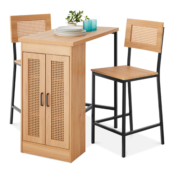
- Page 1 INSTRUCTION MANUAL 3-Piece Dinette Set with Side Cabinet SKY6645 Ver. 1...
-
Page 2: Tools Required
NOTICE Please retain these instructions for future reference. • Please do not exceed the weight limitations of this item. • Do not stand on or use any part of this item as a step ladder. • Firmly secure all bolts, screws, and knobs before use. •... - Page 3 HARDWARE M8 x 45mm M6 x 30mm M6 x 40mm DOOR HINGE SCREW SCREW SCREW 1 PC 16 PCS 12 PCS 4 PCS PARTS TABLETOP CABINET BACK CABINET SIDE I 1 PC 1 PC 1 PC CABINET SIDE II CABINET BOTTOM CABINET BOTTOM PANEL FRAME...
- Page 4 PARTS CABINET TOP FRAME BACKREST SEAT 1 PC 2 PCS 2 PCS TABLE LEGS CHAIR SIDE I CHAIR SIDE II 1 PC 2 PCS 2 PCS CHAIR FRONT FRAME FOOTBAR CHAIR BACK FRAME 2 PCS 2 PCS 2 PCS TABLE SUPPORT BAR 1 PC...
- Page 5 PRODUCT ASSEMBLY Insert two part A cam bolts and two part C dowels into the part 5 cabinet bottom panel. Insert two part B cam locks into the part 6 cabinet bottom frame, then attach it to the part 5 panel.
- Page 6 PRODUCT ASSEMBLY Insert three part B cam locks into the part 2 cabinet back, then attach it to the part 3 cabinet side (see previous step). Turn the cam locks to secure. Use a screwdriver to turn the cam lock to secure the cam bolt.
- Page 7 PRODUCT ASSEMBLY Insert three part B cam locks into the part 2 cabinet back. Insert two part B cam locks each into the part 10 cabinet top frame, part 6 cabinet bottom frame, and part 5 cabinet bottom, six locks total. Attach the part 4 cabinet side to the cabinet assembly.
- Page 8 PRODUCT ASSEMBLY Place the part 1 tabletop on a flat, padded Attach the cabinet to the tabletop, then turn surface with the bottom facing upward. the cam locks to secure. Locate the cabinet assembly and insert three Attach the part 13 table legs to the tabletop part B cam locks into both the part 3&4 with two part L screws.
- Page 9 PRODUCT ASSEMBLY Insert four part I cabinet feet into the bottom of the cabinet assembly. Attach the part 19 support beam to the part 2 cabinet back with two part K screws, then attach the part 13 table legs with one part M screw. Flip the assembly upright, then attach two part F magnetic fasteners to the part 5 cabinet bottom with four part...
-
Page 10: Back View
PRODUCT ASSEMBLY Locate the part 8&9 cabinet doors, then attach two part D handles with four part J screws, two screws per handle. Turn the part 8&9 cabinet doors around and attach two part G fastener plates with four part H screws, two screws per plate. BACK VIEW Insert two part P door hinges into each cabinet door, then insert the doors into the cabinet assembly. - Page 11 PRODUCT ASSEMBLY Attach one part 18 chair back frame, one part 16 chair front frame, and one part 17 footbar to one part 14 chair frame with three part O screws. Attach one part 15 chair frame to part 16, 17, and 18 with three part O screws. Repeat to assemble a second chair frame.
-
Page 12: Help Center
HELP CENTER Question about your product? We're here to help. Visit us at: help.bestchoiceproducts.com CHAT Chat Support Product Inquiry Orders FAQ Product Assembly Returns & Refunds PRODUCT WARRANTY INFORMATION All items can be returned for any reason within 60 days of the receipt and will receive a full refund as long as the item is returned in its original product packaging and all accessories from its original shipment are included.
Need help?
Do you have a question about the SKY6645 and is the answer not in the manual?
Questions and answers