Advertisement
AN1244
AN1274
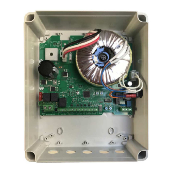
Control box
User and Installation Manual
Basic safety rules must always be respected including those contained in this user guide; not applying these
instructions may provoke damages, injuries or even death.
KEEP THIS MANUAL FOR FUTURE REFERENCE
DATE
08/2020
05/2021
Réf : 004057-02
VERSION
01
AN1244A/AN1274A
02
Modifications alarms, SWx
ZAC de Montrambert - Pigeot, 42150 La Ricamarie – France
Tél : 04 77 33 36 96 - Fax : 04 77 34 12 01
Email : transmission@unicum.fr -
WARNING
MODIFICATIONS
User and installation manual
www.unicum.tech
Page : 1/17
Advertisement
Table of Contents

Summary of Contents for Unicum AN1244
- Page 1 User and installation manual ZAC de Montrambert - Pigeot, 42150 La Ricamarie – France Tél : 04 77 33 36 96 - Fax : 04 77 34 12 01 Email : transmission@unicum.fr - www.unicum.tech AN1244 AN1274 Control box User and Installation Manual WARNING Basic safety rules must always be respected including those contained in this user guide;...
-
Page 2: Important Security Instructions
User and installation manual Important security instructions WARNING FOR YOUR SECURITY – Product installation must be performed by a qualified and authorized technician who has been trained to swimming pool equipment installation. Before installing this product, please read the whole user manual and follow all instructions paying particular attention to warnings that may prevent product failure or other material damages. -
Page 3: Technical Specifications
User and installation manual Technical specifications This control box is compatible with following motors: AN1244: PL3210, PL1218, DL3010 and DL1318 AN1274: PL6010, PL3218, PL7710, DL6010, DL7710 and DL3018 • « Pulse mode » or « Hold mode » can be selected independently on both directions (open/close). -
Page 4: Installation
User and installation manual Installation WARNING FOR YOUR SECURITY – Installation must be performed by an authorized and trained technician following NF-C 18-510 or EN 50110-1. Definition of a qualified installation technician as per NF C 18-510: « professional having a proven technical culture, knowledge and experience and training in electricity allowing him to analyse electrical risks thus avoiding related dangers ». - Page 5 User and installation manual Control device installation 1.2.1. Three positions key switch 1.2.1.1. Key switch characteristics: Key switch must respect to local electrical security standards and regulations. Electrical symbol for key switch Key switch must be IP65 waterproof in order to allow an outdoor installation, close to the pool. Example of limit switch The key switch must have a good quality and must prevent any possible false contacts that may degrade its normal operation.
- Page 6 User and installation manual Electrical cable wiring WARNING All electrical connections have to be made with DC power OFF. Auxiliary Sensor 230VAC relay monophasic (Electroliser) mains Motor network Key switch Safety loop WARNING FOR YOUR SECURITY – Installation must be performed by an authorized and trained technician following NF-C 18-510 or HD 384-7-702 in Europe.
- Page 7 User and installation manual NOTE: submerged cable can’t be repaired nor being connected to others inside « zone 0 ». Zone 2 Zone 1 Zone 0 230VAC AC monophasic cable: An electrical separation device must be settled upstream the control box. It must be easily reachable and found and should be locked in open position.
-
Page 8: Auxiliary Relay
User and installation manual 2 wires sensor 3 wires sensor • Pass the cable through a cable gland. Checking correct sensor cabling: Green LED « S1» displays sensor signal. Motor stopped: led off or on (not blinking). Motor running with correct sensor cable wiring: led flashes with regular frequency. ... - Page 9 User and installation manual Emergency stop Water level sensor Motor: Use for connection one cable 2 wires type HO7 RN-F, 4 mm² section (minimum) and up to 10mm² depending on the distance between motor and control box. Motor cable colours: red and grey wires. To be connected to MOTOR terminal block (positions 1 et 2) Pass the cable through a cable gland.
-
Page 10: General Information
User and installation manual Control box configuration and programming General information Power-on switch To power-on the control box, press the red switch on the side and put on position « I » The switch will light up and the board run its start-up sequence. During board initialization procedure you’ll see code «... - Page 11 User and installation manual INFO/ALARM Display Blinking Start-up procedure ongoing. Automatic Mode. Blinking Unused. Unused. Blinking Limit switch programming to be done Unused. Blinking Unused. Safety loop open. Blinking Sensor defect. Sensor power supply problem Blinking Unused. Fuse « F1 » to be replaced. Blinking Important Archimede force.
-
Page 12: Programming Mode
User and installation manual Programming mode (to be used by qualified personnel) This mode allows limit switch programming thus fixing pool cover working cycle and distance to run. Programming procedure: 1. Move and set the cover to the correct open position (pool completely open) (use MANU mode if necessary). This position will be recorded as zero;... -
Page 13: Manual Mode
User and installation manual Factory setting is OFF (micro-switch 1 on SW1 set to OFF) corresponding to hold mode for open device. This function is inactive when control box is in « MANUAL » or « PROGRAMMATION » even if the dip-switch is set to ON. -
Page 14: Sensor Defect
User and installation manual Operator will be allowed to move the cover using one of the available control devices. « orange » LED indicates « MANUEL » mode The user has to pay the maximum attention in order not to damage the cover. In MANUAL mode the control is completely manual so no automatic stop or overload check is done. - Page 15 User and installation manual In this case please verify sensor connections on terminal block. If alarm persists even disconnecting completely sensor cable, please contact our service team. Fuse fault INFO/ALARM display will show « » fix. Verify pool cover status and cabling before restarting the motor. In case of defect, change motor fuse Motor fuse Important Archimede force INFO/ALARM display will show «...
-
Page 16: Maintenance
User and installation manual Intervention (to be done by qualified personnel only) WARNING Important: when main power switch is on position « O » (no backlight), all board is out of tension except for the area marked « SOUS TENSION ». WARNING Before any intervention on the control box, cut main power supply and wait at least 15 seconds to allow proper discharge of capacitors. -
Page 17: Warranty Application
User and installation manual In MANUAL and PROGRAMMING mode « SW5 » and « SW6 » respectively close and open the cover in hold mode, no matter the configuration on micro-switches 1 et 2 of « SW1 ». In AUTOMATIC mode buttons control cover movement in hold or pulse mode depending on setting done on micro- switches 1 et 2 of «...
Need help?
Do you have a question about the AN1244 and is the answer not in the manual?
Questions and answers