Table of Contents
Advertisement
Quick Links
Advertisement
Table of Contents

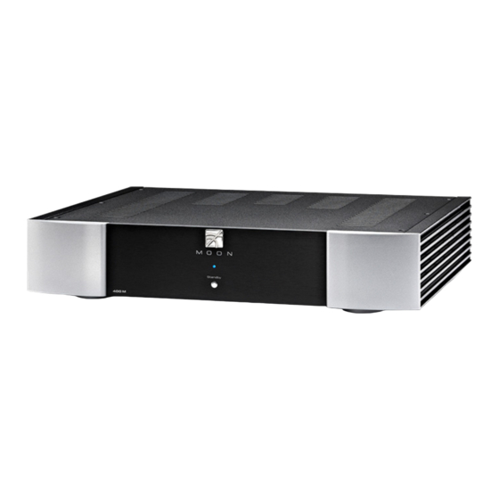
Summary of Contents for Simaudio moon 400M Neo Series
- Page 1 400M Series Mono Power Amplifier Owner’s Manual...
- Page 2 400M Neo Series...
- Page 3 Owner’s Manual Important Safety Instructions Read these instructions. receptacles, and the point where they exit from the apparatus. Unplug mains cord during Keep these instructions. transportation. Heed all warnings. 11. Only use attachments and accessories specified by Follow all instructions. the manufacturer.
- Page 4 400M Neo Series Important Safety Instructions (cont’d) The lightning flash with the arrowhead symbol, within an equilateral triangle, is intended to alert the user to the presence of uninsulated “dangerous voltage” within the product’s enclosure that may be of sufficient magnitude to constitute a risk of electric shock to persons.
-
Page 5: Table Of Contents
Owner’s Manual Table of Contents Introduction Unpacking Installation & Placement Rear Panel Layout Connecting the Nēo 400M Balanced Operation Operating the Nēo 400M Remote Operation Specifications www.simaudio.com Simaudio Ltd., 1345 Newton Road Boucherville, Québec J4B 5H2 CANADA Date Code: 20150203... -
Page 6: Introduction
Simaudio has made its reputation. We have spared no effort to ensure that it is among the finest two-channel Balanced differential circuitry. amplifiers available. -
Page 7: Unpacking
Owner’s Manual Unpacking The Nēo 400M power amplifier should be removed from its box with care. The following accessories should be included inside the box with your amplifier: AC power cable This owner’s manual Warranty and product registration information (USA and Canada only) Once the Nēo 400M is unpacked, inspect it thoroughly and report any damage to your dealer immediately. -
Page 8: Rear Panel Layout
400M Neo Series Rear Panel Layout Figure 1: Nēo 400M Rear panel The rear panel will look similar to Figure 1 (above). There is one balanced (differential) input on an XLR connector and one unbalanced (single-ended) input on a RCA connector. There is no switch to toggle from balanced mode to single-ended mode. -
Page 9: Connecting The Nēo 400M
Owner’s Manual Connecting the 400M Connect the supplied AC power cable to the IEC receptacle, located on the amplifier’s rear panel. Ensure that the AC wall outlet you use has a Prior to making any connections or removing the XLR functioning ground. -
Page 10: Operating The Nēo 400M
400M Neo Series your 400M on or off, you should always power up your Operating the 400M preamplifier prior to powering up your 400M. As well, always power down your 400M prior to powering down We recommend leaving your Nēo 400M powered up at your preamplifier. -
Page 11: Remote Operation
Owner’s Manual Remote Operation Figure 3: Remote Operation In figure 3 we have a Nēo 350P Preamplifier and a pair of 400M Amplifiers connected together via their respective 12V triggers; The 12V trigger output on the 350P is connected to the 12V trigger input on the top 400M (using a 1/8”... -
Page 12: Specifications
Pin 3 Negative NOTE: If you require the RS-232 codes for your Nēo 400M, please visit the "Contact Us" page and complete the "Information request" form on our website at www.simaudio.com. Fuse Replacement: 120V version uses a 8A fast blow (3AG) - Page 13 Owner’s Manual...
- Page 14 400M Neo Series...


Need help?
Do you have a question about the moon 400M Neo Series and is the answer not in the manual?
Questions and answers