Table of Contents
Advertisement
Quick Links
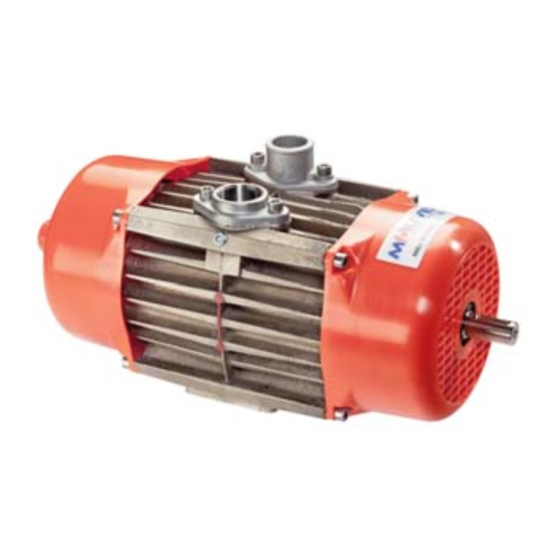
E140
The EC Certificate of Conformity (paper version) is systematically attached to the equipment when shipped.
ENTERPRISE compressors are covered 24 months by warranty within the limits mentioned in our General Sales
Conditions. In case of a use other than that mentioned in the Instructions manual, and without preliminary agreement of
MOUVEX, warranty will be canceled.
Z.I. La Plaine des Isles - F 89000 AUXERRE - FRANCE
Tel. : +33 (0)3.86.49.86.30 - Fax : +33 (0)3.86.49.87.17
contact.mouvex@psgdover.com - www.mouvex.com
ENTERPRISE
E140 - E170
E170
E140 HYD
EC CERTIFICATE OF CONFORMITY :
WARRANTY :
INSTRUCTIONS 208-A00 e
Section
208
Effective
March 2023
Replaces
February 2018
Original instructions
INSTALLATION
OPERATION
MAINTENANCE
Your distributor :
Advertisement
Table of Contents

Related Manuals for Dover PSG Mouvex Enterprise E140


Summary of Contents for Dover PSG Mouvex Enterprise E140
- Page 1 INSTRUCTIONS 208-A00 e Section Effective March 2023 Replaces February 2018 Original instructions ENTERPRISE E140 - E170 E140 E170 INSTALLATION OPERATION E140 HYD MAINTENANCE EC CERTIFICATE OF CONFORMITY : The EC Certificate of Conformity (paper version) is systematically attached to the equipment when shipped. WARRANTY : ENTERPRISE compressors are covered 24 months by warranty within the limits mentioned in our General Sales Conditions.
-
Page 2: Table Of Contents
MOUVEX ROTARY VANE COMPRESSORS INSTALLATION, OPERATION, AND MAINTENANCE INSTRUCTIONS MODELS : E140 - E170 Definition of safety symbols Page TABLE OF CONTENTS This is a SAFETY ALERT SYMBOL. When you see this symbol on the product, or in the manual, look for one of the following signal words and be alert to the 1. - Page 3 SAFETY DATA SAFETY CHECKLIST WARNING 1. Before operating the compressor, ensure the vessel to COMPRESSING GASES INTO A VES- which the compressor is connected is certified to withstand SEL CONTAINING FLAMMABLE OR the pressure and /or vacuum produced. EXPLOSIVE GASES OR COMPRESSING FLAMMABLE OR EXPLOSIVE GASES, CAN CAUSE PROPERTY DAMAGE, 2.
-
Page 4: Overall Dimensions
1. OVERALL DIMENSIONS 1.1 E140 NT 208-A00 03 23 Enterprise e 4/19... -
Page 5: E170
1. OVERALL DIMENSIONS (continued) 1.2 E170 NT 208-A00 03 23 Enterprise e 5/19... -
Page 6: Technical Data
2. TECHNICAL DATA E140 E170 Models Compressor Operating Limits 82 cfm 102 cfm Speed - rpm Maximum Air (140 m (173 m 1800 36 kg 47 kg Weight 1600 (79 lbs) (104 lbs) 1400 11,5 PS 13,7 PS Power absorbed* (8,5 kW) (10,2 kW) 1200... -
Page 7: Drive Systems
3. INSTALLATION (continued) 3.2 Drive systems 3. Ensure that the compressor rotates in the direction of the arrows cast on the body. See Figure 3. A variety of drive options are available for the compres- sor, including vehicle mounted, drive shaft, hydraulic motor and flexible coupling. -
Page 8: Drive Shaft - See Figure 5
3. INSTALLATION (continued) 3.3 Drive shaft - See Figure 5 3.4 Hydraulic drive 1. If the compressor is to be driven hydraulically, WARNING MOUVEX can supply a standard Drive Kit for direct mounting of the hydraulic motor or hydraulic pump. MOUVEX can also supply the hydraulic motor ;... -
Page 9: Piping
3. INSTALLATION (continued) 3.5 Piping Assembling procedure : 1. Piping MUST be at least as large as the compressor • To cut the hose to the length requested. suction and discharge connections. • To fold back the end of the wire inside. ALL piping MUST be adequately supported to prevent any piping loads from being placed on the compressor. - Page 10 3. INSTALLATION (continued) • To assemble the unit on the compressor inlet port and 3. The compressor MUST have an adequately sized to tighten the clamp : aluminium flange. pressure relief valve installed approximately 30 inches after the compressor discharge ; See figure 8. Example with B200 : Relief/Check Valve - Mount where proper operation can be observed...
-
Page 11: Use
4. USE WARNING Close all valves and proceed to pressurize the tank and discharge the cargo. COMPRESSING GASES INTO A VES- SEL CONTAINING FLAMMABLE OR EXPLOSIVE GASES OR COMPRESSING FLAMMABLE OR EXPLOSIVE GASES, CAN CAUSE PROPERTY DAMAGE, PERSONAL INJURY OR DEATH. Hazardous gases CLOSED can cause property... -
Page 12: Maintenance
5. MAINTENANCE WARNING WARNING FAILURE TO SET THE VEHICLE EMER- FAILURE TO RELEASE ALL SYSTEM AIR GENCY BRAKE AND CHOCK WHEELS AND WHEN EQUIPPED, HYDRAULIC BEFORE PERFORMING SERVICE CAN PRESSURE, CAN CAUSE PROPERTY CAUSE SEVERE PERSONAL INJURY DAMAGE, PERSONAL INJURY OR DEATH. OR PROPERTY DAMAGE. -
Page 13: Quick Blade Inspection (E140 Only)
5. MAINTENANCE (continued) 5.1.2 BLADE INSPECTION 5.3 Sideplate removal 1. Disconnect the compressor from the driver and remove For typical applications blades should be inspected every the shaft key (16). 1000 hours, and replaced if worn below 1.57” (40 mm). See Figure 9. -
Page 14: Blade Removal And Inspection
5. MAINTENANCE (continued) 5.4 Blade removal and inspection 7. Reassemble compressor in reverse order to disman- tling. All internal surfaces of body, rotor, blades and 1. Thoroughly clean end of machine to be dismantled. sideplates must be free of oil or grease. When reas- Care must be taken during inspection that no dirt, oil sembling, replace all O-rings that have been removed or grease enters the machine. -
Page 15: Sideplate Disassembly
5. MAINTENANCE (continued) 5.6 Sideplate disassembly 5.7 Sideplate assembly 1. Remove the three M10 screws (11) securing the bearing 1. Before starting, place the sideplate (1) face down on cap, and remove the bearing cap (2) ; See figure 16. a flat, clean surface. -
Page 16: Setting Sideplate Clearance
5. MAINTENANCE (continued) 5.8 Setting sideplate clearance 5. From the rotor side, push in the distance sleeve (3), through both seals, until it is flush with the face of the 1. Prior to attaching the sideplate to the compressor sideplate ; See figure 21. body, check the end clearance between the rotor and sideplate using two feeler gauge strips. -
Page 17: Compressor Assembly
5. MAINTENANCE (continued) 5.9 Compressor assembly 5. Install second sideplate assembly as instructed in step 2 above. See figure 27. 1. Stand the compressor body, ports down, on “V” blocks or packing as shown in Figure 25. Use care during the M8 shoulder screw (9) assembly process to avoid any contamination. -
Page 18: Initial Start Up / Reinstallation
5. MAINTENANCE (continued) 5.10 Initial start up / Reinstallation 4. After start-up, verify the following : • Check compressor speed. Compressor speed must NOTICE : fall within the operating parameters indicated in the FOLLOW ALL HAZARD WARNINGS AND NOTICES IN THE § §... -
Page 19: Compressors Form Information
8. COMPRESSORS FORM INFORMATION Before any material return, it is required to get an authorization from MOUVEX. COMPRESSORS FORM INFORMATION MOUVEX Tel : (33) 3 86 49 86 03 Date : After Sales Department Z.I. de la Plaine des Isles Fax : (33) 3 86 49 86 48 Contact : 89000 AUXERRE...
Need help?
Do you have a question about the PSG Mouvex Enterprise E140 and is the answer not in the manual?
Questions and answers