
Related Manuals for Airflow Entro-V Controls


Summary of Contents for Airflow Entro-V Controls
- Page 1 80001022 – Issue 2 01/22 Entro-V Controls Part No: 90001308/90001299 BASIC CONTROLLER, DIGITAL CONTROLLER AND OTHER CONTROL OPTIONS User and installation manual V1.2 01.11.2021...
-
Page 2: Table Of Contents
AIRFLOW User Manual 01.11.2021 Contents PART I – GENERAL DEFINITIONS .......................4 1. General Information ............................. 4 1.1. Introduction .............................. 4 1.2. Functions ..............................5 1.3. Product Description & Code ........................7 2. Control Board ............................... 8 2.1. Control board technical information ......................8 2.2. - Page 3 AIRFLOW User Manual 01.11.2021 4.1. By-Pass Control ............................ 30 4.2. Rotor Control ............................30 5. Heating & Cooling Control......................... 31 5.1. Electric Heater Control [HT] ........................31 5.2. Water Coil Control [CW] ........................31 5.3. Heating-Cooling System with Refrigerant (DX System) [DX] ..............32 6.
- Page 4 AIRFLOW User Manual 01.11.2021 Abbreviations & Acronyms Analogue Input Fire info (DI) Analogue output Heat recovery frost protection scenario Unit run function (dry contact) (DI) DX system 4-way valve (DO) “Boost” function (DI) Heater By-Pass damper (DO) Heater 1 stage (DO)
-
Page 5: Part I - General Definitions
AIRFLOW User Manual 01.11.2021 PART I – GENERAL DEFINITIONS 1. General Information 1.1. Introduction Lately, most of our life is spent indoors (at home, office, etc) and indoor air quality has become a very important topic. To help reducing the indoor air pollution, heat recovery units have been designed. -
Page 6: Functions
AIRFLOW User Manual 01.11.2021 1.2. Functions Function Definition It provides control of the speed of fans. • Manual: 3 steps fan speed control for EC or AC fans o Single fan mod Fan Speed Control o Individual speed control of the fans •... - Page 7 AIRFLOW User Manual 01.11.2021 Function Definition Heat exchanger frost protection • Alternative-1: By-Pass damper Frost Protection Function • Alternative-2: Fan speed control • Alternative-3: Electric Preheater steps control Preheater Function Electric preheater steps control for frost protection. Enables selection of return air temperature or control controller temperature Room Temperature Function as room temperature.
-
Page 8: Product Description & Code
AIRFLOW User Manual 01.11.2021 1.3. Product Description & Code Code Description Equipment view Control board PWM control & 90001522 Terminal connection (Part I – Section 2.3.1) Control board PWM control & 90001315 Socket connection (Part I – Section 2.3.2) Basic controller 90001308 (Part I –... -
Page 9: Control Board
AIRFLOW User Manual 01.11.2021 2. Control Board 2.1. Control board technical information Power supply : 230V AC ±15%, 50 ~ 60Hz Power consumption : 5W (max) Working condition : 0 ~ 50°C, %90RH (max) (no condensation) Storage condition : -20 ~ 70°C... - Page 10 AIRFLOW User Manual 01.11.2021 V1.2 9 / 50...
- Page 11 AIRFLOW User Manual 01.11.2021 V1.2 10 / 50...
- Page 12 AIRFLOW User Manual 01.11.2021 V1.2 11 / 50...
-
Page 13: Control Board Alternatives
AIRFLOW User Manual 01.11.2021 2.3. Control board alternatives 2.3.1. PWM control & TERMINAL connection (90001522) Equipment view Dimensions V1.2 12 / 50... - Page 14 AIRFLOW User Manual 01.11.2021 V1.2 13 / 50...
-
Page 15: Pwm Control & Socket Connection (90001315)
AIRFLOW User Manual 01.11.2021 2.3.2. PWM control & SOCKET connection (90001315) Equipment view Dimensions V1.2 14 / 50... - Page 16 AIRFLOW User Manual 01.11.2021 V1.2 15 / 50...
-
Page 17: Controllers
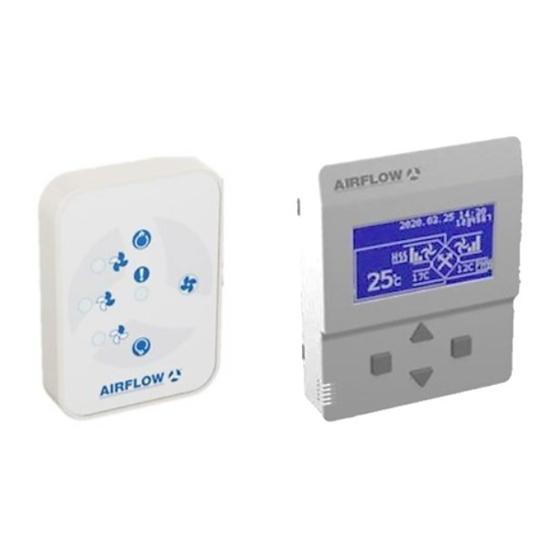
AIRFLOW User Manual 01.11.2021 3. Controllers 3.1. Basic Controller (90001308) The Basic Controller was designed to allow the user to simply control all the basic functions of the unit. There are 3 basic buttons and 4 LEDs on it. Equipment view... -
Page 18: Leds
AIRFLOW User Manual 01.11.2021 3.1.2. LEDs Description Unit powered off Fan speed is “high”. Fan speed is “med”. Fan speed is “low”. Fan speed is “boost”. VOD mode is active. Fire function is active. Failure warning (see Part III). Led is off... -
Page 19: Surface Mounting
AIRFLOW User Manual 01.11.2021 3.1.4. Surface mounting V1.2 18 / 50... -
Page 20: Digital Controller (90001299)
AIRFLOW User Manual 01.11.2021 3.2. Digital Controller (90001299) The Digital Controller was designed to control all the functions of the unit and to change settings related to the unit. It has 4 buttons and 1 graphic display. Equipment view Dimensions... -
Page 21: Screenshots
AIRFLOW User Manual 01.11.2021 Cannot change the fan speed if “Boost” function is active Reset works if the unit is off Cannot work if the unit has filter sensor 3.2.2. Screenshots 1.Screen 4.Screen Main Screen Adjust 5.Screen 2.Screen Company Timer Logo 3.Screen... - Page 22 AIRFLOW User Manual 01.11.2021 1.Symbol: Fresh Air Fan 2.Symbol: Exhaust Air Fan Fan speed “low” Fan speed “low” Fan speed “med” Fan speed “med” Fan speed “high Fan speed “high Fan speed “boost” Fan speed “boost” VOD mode is active VOD mode is active 3.Symbol: Heat exchanger (Plate or Rotor) &...
- Page 23 AIRFLOW User Manual 01.11.2021 4.Symbol Controller temperature (T_PA). Temperature set value when selected. 5.Symbol Return air temperature (T_RA) 6.Symbol Outdoor air temperature (T_OA) 7.Symbol Supply air temperature (T_SA). (If sensor is available) 8.Symbol: Preheater Not available Type: Preheater Status: Off...
- Page 24 AIRFLOW User Manual 01.11.2021 “2.Screen” Symbols: Timer Info Input 1.Field Day of the week selection 2.Field Fan mode selection 3.Field Clock selection 4.Field System time information “3.Screen” Symbols: Information Info Input 1.Field Temperature sensor values [°C] 2.Field Sensor values [mV] 3.Field...
- Page 25 AIRFLOW User Manual 01.11.2021 “4.Screen” Symbols: Settings Info Input 1.Field Date setting [YYYY.MM.DD] 2.Field Clock setting [HH:MM] day of the week selection. For example, if the 1st day of the week is Monday and today is Wednesday, the entry 3.Field...
-
Page 26: Cable Connection
AIRFLOW User Manual 01.11.2021 3.2.3. Cable connection Cable type: Cat6 Maximum length: 50m +12V : blue & blue-white GND : brown & Brown-white : orange-white : orange V1.2 25 / 50... -
Page 27: Surface Mounting
AIRFLOW User Manual 01.11.2021 3.2.4. Surface mounting V1.2 26 / 50... -
Page 28: Accessories
AIRFLOW User Manual 01.11.2021 4. Accessories 4.1. Sensors 4.1.1. Temperature Sensor (90001316) NTC 10kΩ (@25°C) type sensor used for air temperature measurement. The control board is calibrated according to this sensor. Duct type sensor is also suitable to use. Appearance... -
Page 29: Carbon Dioxide
AIRFLOW User Manual 01.11.2021 4.1.3. Carbon dioxide (CO ) Sensor (90001319) It is the sensor used to measure the amount of carbon dioxide (CO ) in the air. The control board is calibrated according to this sensor. Duct type sensor is also suitable to use. -
Page 30: Part Ii - Working Scenario
AIRFLOW User Manual 01.11.2021 PART II – WORKING SCENARIO 1. Fan Speed Control Control Board: F_OA, F_RA, C_OA, C_RA Control Controller: Fan speed selection Description Register Default Mode selection “standard” Alarm type selection for fresh air fan “tacho” Alarm type selection for fresh air fan “tacho”... -
Page 31: Filter Control
AIRFLOW User Manual 01.11.2021 3. Filter Control Control Board: DI (FI1, FI2) Control Controller: --- Description Register Default Filter-1 fouling time reference 3000 Filter-2 fouling time reference 3000 Control Board DI5 Selection “FI1” Filters on the device must be cleaned at certain times. It is the function that indicates the time of cleaning. -
Page 32: Heating & Cooling Control
AIRFLOW User Manual 01.11.2021 It is used to control the motor of the rotor on/off in ventilation units with rotor type heat recovery exchanger. In the transition seasons, it is better not to use the heat recovery rotor in terms of energy saving and comfort when the temperature of the outdoor air drops during the summer hours or the temperature of the outdoor air rises at noon in the winter. -
Page 33: Heating-Cooling System With Refrigerant (Dx System) [Dx]
AIRFLOW User Manual 01.11.2021 Depending on the purpose of use, heating (HEAT), cooling (COOL) or heating & cooling (AUTO) operation can be selected. There is a fault input for the water coil (dry contact NC). If this connection is made, a malfunction in the water coil will be shown on the control controller and will disable the water coil. -
Page 34: Room Temperature Sensor Function [T_Ro]
AIRFLOW User Manual 01.11.2021 Pre-heater method: If a pre-heater is mounted on fresh air duct, it will be activated. There is a fault input for the electric heater (dry contact NC). If this connection is made, a malfunction in the electric heater will be shown on the control controller and will disable the electric heater. -
Page 35: Modbus Function
AIRFLOW User Manual 01.11.2021 9. Modbus Function It is the function that controls all the functions and settings of the device through the Building Management System. 9.1. Properties Control board uses Modbus RTU protocol via RS485 connection. The unit works as Slave and the information can be taken from an external Master module. -
Page 36: Modbus Register List
AIRFLOW User Manual 01.11.2021 Corresponding response value of control board is shown on the table below. In the second example, master wants to write the 16 bit data on 2 register and it is reported to control board that the data was written. - Page 37 AIRFLOW User Manual 01.11.2021 Definition Description Processed data of input SE1 Part I – 1.Sensor real value Section 4.1) Processed data of input SE2 Part I – 2.Sensor real value Section 4.1) RF 1.Sensor real value Processed data of RF1 input RF 2.Sensor real value...
-
Page 38: Timer Function
AIRFLOW User Manual 01.11.2021 Definition Description Control Board DI3 input [0,1] 0-Off / 1-On Control Board DI4 input [0,1] 0-Off / 1-On Control Board DI5 input [0,1] 0-Off / 1-On Mode selection [0,1] 0- Standard fan speed / 1- VOD... -
Page 39: Unit Status When Power On
AIRFLOW User Manual 01.11.2021 Alternative-1: Manual: Optionally, the function can be activated and deactivated by pressing the key combination on the control controller. Alternative-2: Time dependent: When this function is activated; The function is activated when the keys are not pressed for a certain period of time. -
Page 40: Part Iii - Alarm (Failure)
AIRFLOW User Manual 01.11.2021 PART III – ALARM (Failure) 1. Fault Info (Fault out) [FLT] The device gives a warning in the event of a malfunction in any of its equipment. The control card decides whether to continue operating according to the severity of the fault. Fault information is transmitted to the user as a fault code in use controllers (Digital Controller, Touch Controller, etc.) and warning led in the Basic... - Page 41 AIRFLOW User Manual 01.11.2021 Description Unit Status Clock malfunction 01101 ERR 13 Time function disabled. necessary Filter-2 pollution [FI2] 10000 ERR 16 Unit run normally. Necessary Service door open [SDI] 10001 ERR 17 Unit off. necessary Fans continue to run. DX...
-
Page 42: Annex.a - Servi̇ce Operations
AIRFLOW User Manual 01.11.2021 ANNEX.A – SERVİCE OPERATIONS 1. Basic Controller BUTTONS Function Button Activity Service operation Press for 3 seconds By-Pass function on/off [BYP] Press for 3 seconds Equipment function on/off (Heater, Press for 3 seconds preheater) [HTI] BMS function on/off [BMS]... - Page 43 AIRFLOW User Manual 01.11.2021 “6.Screen” Symbols: Password screen (Password is 1919) Info Input 1.Field Password entry “7.Screen” Symbols: I/O configure screen Info Input 1.Field Outputs selection (dry contact) (DO) 2.Field Power output selection 3.Field Inputs selection (dry contact) (DI) 4.Field...
- Page 44 AIRFLOW User Manual 01.11.2021 Outputs Code List (DO) Code Description Code Description Rotor heat exchanger (Part II – Section Not connected 4.2) Unit run out info (Run out) (Part II – Ultraviolet lamp Section 8.2) Failure info (Fault out) (Part II – Section Water coil (Part II –...
-
Page 45: Register List
AIRFLOW User Manual 01.11.2021 4. Register List Column Name Description Modbus It can be used in Modbus connection It records on the controller Register number Definition Definition Multiplier Multiplier coefficient of register value Access Knowledge of writing and reading authority (r: Read only, rw: Read and write) - Page 46 AIRFLOW User Manual 01.11.2021 Definition Description 1.Sensor value 0,01 Voltage value of SE1 2.Sensor value 0,01 Voltage value of SE2 RF 1.Sensor value 0,01 Voltage value of SR1 RF 2.Sensor value 0,01 Voltage value of SR1 Processed data of input SE1 (only 1.Sensor real value...
- Page 47 AIRFLOW User Manual 01.11.2021 Definition Description DX system frost protection [0,1] 0-Off / 1-On [FDF] Control Board DO1 Output [0,1] 0-Off / 1-On Control Board DO2 Output [0,1] 0-Off / 1-On Control Board LP0 Output [0,1] 0-Off / 1-On Control Board LP1 Output...
- Page 48 AIRFLOW User Manual 01.11.2021 Definition Description 0-Low / 1-Med / 2-High / 3- Exhaust air fan speed stage [0,3] Stop Alarm type selection for [0,2] 0-Tacho / 1-NC / 2-NO fresh air fan Alarm type selection for [0,2] 0-Tacho / 1-NC / 2-NO...
- Page 49 AIRFLOW User Manual 01.11.2021 Definition Description 0-Passive 1-By-Pass Frost protection status [0,1] 2-FAN_OA “off” 3-FAN_OA”low” FAN_RA”high” Frost temperature °C [-10,10] Frost protection scenario [5,50] runtime Child proof protection [0,1] 0-Manual / 1-Automatic method selection Unit status when power on [0,1]...
- Page 50 [0,6000] filter-2 Working time count for [0,6000] ultraviolet lamp Airflow Developments Limited info@airflow.com Aidelle House, Lancaster Road, Cressex T: 44(0)1494 525252 Business Park, High Wycombe W: airflow.com Buckinghamshire, HP12 3QP, U.K ©Copyright 2016. Airflow Developments Ltd V1.2 49 / 50...
Need help?
Do you have a question about the Entro-V Controls and is the answer not in the manual?
Questions and answers