Table of Contents
Advertisement
Quick Links
1
GENERAL WARNING
1.1 PLEASE READ BEFORE USING THIS MANUAL
•
This manual is part of the product and should be kept near the instrument for easy and quick reference.
•
The instrument shall not be used for purposes different from those described hereunder. It cannot be used as a safety device.
•
Check the application limits before proceeding.
1.2 SAFETY PRECAUTIONS
•
Check the supply voltage is correct before connecting the instrument.
•
Do not expose to water or moisture: use the controller only within the operating limits avoiding sudden temperature changes with high atmospheric humidity to prevent formation of condensation
•
Warning: disconnect all electrical connections before any kind of maintenance.
•
Fit the probe where it is not accessible by the End User. The instrument must not be opened.
•
In case of failure or faulty operation send the instrument back to Weiss Instruments (see address) with a detailed description of the fault.
•
Consider the maximum current which can be applied to each relay (see Technical Data).
•
Ensure that the wires for probes, loads and the power supply are separated and far enough from each other, without crossing or intertwining.
•
In case of applications in industrial environments, the use of mains filters (our mod. FT1) in parallel with inductive loads could be useful.
•
Dixell reserves the right to change the composition of its products, even without notice, ensuring the same and unchanged functionality.
2
GENERAL DESCRIPTION
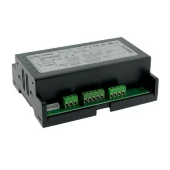
Model XW60K is microprocessor based controller suitable for applications on medium or low temperature refrigerating units. It has to be connected by means of a two-wire cable18-24 gauge, at a distance of up to 100 Ft. to
the keyboard T620T or T620 or VX620 or CX620. It is provided with four relay outputs to control Liquid Line solenoid, defrost (which can be either electrical or hot gas), the evaporator fans and light or Alarm. It is also
provided with up to 4 NTC or PTC probe inputs, one for temperature control, one to control the defrost end temperature and evaporator fan control and the third for Discharge Air (required for On Demand defrost) and fourth
to control condenser temperature or to display another temperature. The control features an On-Demand Defrost.
The HOT KEY output allows connecting the unit, by means of the external module XJ485-CX, to a network line ModBUS-RTU compatible such as the dIXEL monitoring units of XWEB family. It allows you to program the
controller by means of a HOT KEY.
The instrument is fully configurable through special parameters that can be easily programmed through the keyboard.
3
CONTROLLING LOADS
3.1 THE LIQUID LINE SOLENOID VALVE
The regulation is performed according to the temperature measured by the thermostat probe P1, placed in the return air stream with a positive differential from the set point: if the temperature increases and reaches set point
plus differential the LLS is opened and then closed when the temperature reaches the set point value again.
In case of a fault in the thermostat probe the start and stop of the LLS are timed through parameters Con and CoF.
3.2 FAST FREEZING – OPTIONAL THROUGH PROGRAMMING
When defrost is not in progress, a continuous chill mode can be activated by holding the oUP key pressed for about 3 sec. The solenoid operates to maintain the CCS set point for the time set through the CCt parameter.
The cycle can be terminated before the end of the set time by pressing theo UP key for 3 sec.
3.3 DEFROST (ON-DEMAND®) OR RTC* OPTIONAL (*MUST BE ORDERED)
Hot Gas or Electric Defrost can be managed through the tdF parameter, electric (tdF = EL) and hot gas defrost (tdF = in).
The EdF parameter determines the defrost interval time type. "in" interval between defrost, "ond" on demand defrost ®, or "rtC" Real Time Clock (optional). Do not select if the control was not ordered with RTC.
-EdF=in: a defrost starts after elapsing the idF time (standard way for controller without RTC).
-EdF=ond the instrument is able to perform an "on demand defrost ®" monitoring pull down time, difference between inlet and outlet temperature and door openings to determine when a defrost is required. idF should be set
to 0. No other adjustments are needed. Enter a manual defrost within the first 12 hours to help recognise the defrost cycle time.
-EdF=rtC: (Optional) defrosts are scheduled by using a real time clock system, depending on the hours set in the parameters Ld1..Ld6, during workdays, and in Sd1...Sd6 during weekends.
Other parameters are used to control defrost cycles: its maximum length (ndF) and two defrost modes: timed or controlled by the evaporator's probe (P2P).
At the end of defrost dripping time is started, its length is set in the Fdt parameter. With Fdt=0 the dripping time is disabled.
3.4 CONTROL OF EVAPORATOR FANS
The fan control mode is selected by means of the FnC parameter:
FnC = C_n: fans will switch ON and OFF with the solenoid and not run during defrost;
FnC = o_n
fans will run even if the solenoid is off, and not run during defrost;
After defrost, there is a timed fan delay allowing for drip time, set by means of the Fnd parameter.
FnC = C_Y fans will switch ON and OFF with the solenoid and run during defrost;
FnC = o_Y
fans will run continuously also during defrost.
An additional parameter FSt provides the setting of temperature, detected by the evaporator probe, above which the fans are always OFF. This is used to make sure circulation of air only if his temper ature is lower than set
in FSt.
3.4.1 Forced activation for fans
This function, managed by the FCt parameter, is designed to avoid short cycles of fans, that could happen when the controller is switched on or after a defrost, when the room air warms the evaporator.
If the difference between the evaporator temperature and the room temperature is higher than the FCt value, the controller will activate the fans. This function is disabled if FCt=0.
3.4.2 Timed activation of the fans when the solenoid is off.
When FnC=C-n or C-Y (fans in parallel to the solenoid), the fans will be able to carry out on and off cycles even if the LLS is closed. The on and off interval of time follow the Fon and FoF parameters. When the LLS is
closed the fans will go on working for the Fon time. On the other side, with Fon=0 the fans will stay always off when the LLS is closed.
4
SPECIAL FUNCTIONS
By means of the parameter oA3, it's possible to configure the functions of the light relay (22-23), as described in the following paragraphs:
4.1 LIGHT RELAY (FACTORY SETTING, OA3 = LIG)
By setting oA3=Lig the relay will work as light relay, it is switched on and off by the light button on the keyboard and is affected by status of the digital input when i1F=dor.
XW60K 110918 V14.7 EMERSON092718 V14.7
XW60K WALK-IN CONTROLLER WITH
ON-DEMAND DEFROST
XW60K
1/12
Advertisement
Table of Contents

Related Manuals for Emerson dixell XW60K


Summary of Contents for Emerson dixell XW60K
- Page 1 XW60K WALK-IN CONTROLLER WITH ON-DEMAND DEFROST GENERAL WARNING 1.1 PLEASE READ BEFORE USING THIS MANUAL • This manual is part of the product and should be kept near the instrument for easy and quick reference. • The instrument shall not be used for purposes different from those described hereunder. It cannot be used as a safety device. •...
- Page 2 The parameter LHt (Light timer) sets the time the light will stay on after pressing the light switch on the keyboard. Every time the key is pushed the timer is re-loaded. 4.2 SECOND SOLENOID MANAGEMENT (OA3 = CP2) OPTIONAL By setting oA3=CP2, the relay at terminals 22-23 will operate as “second solenoid”. It will be activated in parallel with the relay of the first solenoid, with a possible delay set in the AC1 parameter (seconds). Both the solenoids are switched off at the same time.
-
Page 3: Use Of Leds
KEYBOARD ICONS To display and modify target set point; in programming mode it selects a parameter or confirm an operation. By holding it pressed for 3 sec when max or min temperature is displayed it will be erased. (UP) To see the max stored temperature; in programming mode it browses the parameter codes or increases the displayed value. -
Page 4: Parameter List
7.2 HOW TO SEE THE MAX TEMPERATURE Press and release the UP key. The “Hi” message will be displayed followed by the maximum temperature recorded. By pressing the UP key or waiting for 5 sec the normal display will be restored. 7.3 HOW TO RESET THE MAX AND MIN TEMPERATURE RECORDED To reset the stored temperature, when max or min temperature is displayed: Press SET key until “rST”... - Page 5 Outputs activation delay at start up: (0 to 255min) this function is enabled at the initial start up of the instrument and inhibits any output activation for the period of time set in the parameter. Anti-short cycle delay: (0 to 50min) minimum interval between the solenoid stop and the following restart. solenoid delay at start up (0to255s) Used only with oA3 or oA4 = cP2 Time interval between the switching on of the first solenoid and the second one.
- Page 6 Differential for temperature alarm recovery: (0.1 to 25.5°C; 1 to 45°F) intervention differential for recovery of temperature alarm. Temperature alarm delay: (0 to 255 min) time interval between the detection of an alarm condition and alarm signaling. Exclusion of temperature alarm at start-up: (0.0 to 24h00min, res. 10min) time interval between the detection of the temperature alarm condition after instrument power on and alarm signaling. CONDENSER TEMPERATURE ALARM Probe selection for temperature alarm of condenser: (nP;...
-
Page 7: Digital Input
Type of probe: (PtC; ntC) it allows to set the kind of probe used by the instrument: PtC = PTC probe; ntC = NTC probe. Energy Pig Key: (nU; oFF; ES) nU = disabled; oFF = On/OFF; ES = Energy Saving Mode Thermostat probe display. -
Page 8: Alarm Signals
13 ALARM SIGNALS Message Cause Outputs Thermostat probe failure Alarm signal ON; Solenoid output according to parameters Con and CoF. Evaporator probe failure Alarm signal ON; Other outputs unchanged Probe 3 probe failure Alarm signal ON; Other outputs unchanged Probe 4 probe failure Alarm signal ON;... -
Page 9: Electrical Connections
15 ELECTRICAL CONNECTIONS XW60K is provided with screw terminal blocks to connect cables with a cross section up to 2.5 mm for the RS485 (optional) and the keyboard. To connect the other inputs, power supply and relays, XW60K is provided with Faston connections (6.3mm). - Page 10 Default Level Label Name Range Outputs activation delay at start up 0 to 255 min Anti-short cycle delay 0 to 30 min Second solenoid delay 0 to 255 sec P1-P2 percentage for regulation 0 to 100 (100=P1 , 0=P2) Solenoid ON time during fast freezing 0.0 to 23h50min, res.
-
Page 11: Auxiliary Output
Default Level Label Name Range Delay of temperature alarm at start up 0.0 to 23h50min, res. 10 min 2.30 Probe for temperat. alarm of condenser nP; P1; P2; P3; P4 [-55.0 to 150.0°C] Condenser for low temperat. alarm [-67 to 302°F] [-55.0 to 150.0°C] Condenser for high temperat. - Page 12 Software release read only Map code read only 18 CERTIFICATIONS 19 FOR WARRANTY AND OTHER INFORMATION 1065 Big Shanty Road Suite 100 Kennesaw, GA 30144 www.emerson.com Support: Phone: (770)425-2724 select option #2. SolutionsTechSup@Emerson.com Sales: solutions.customerservice@emerson.com LINK LINK XW60K 110918 V14.7 EMERSON092718 V14.7...
Need help?
Do you have a question about the dixell XW60K and is the answer not in the manual?
Questions and answers