
Related Manuals for Quatech DSC-100


Summary of Contents for Quatech DSC-100
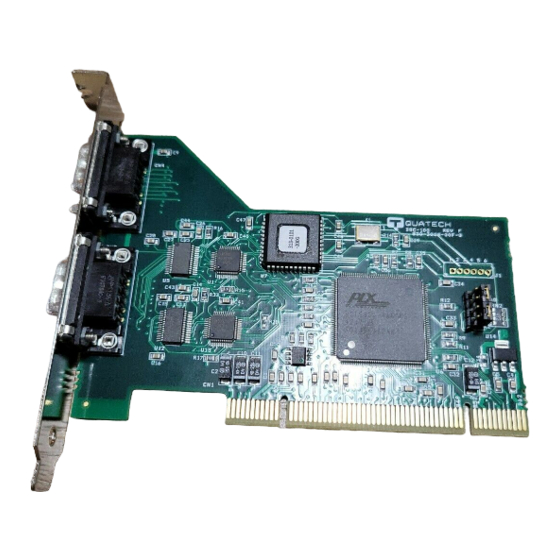
- Page 1 Two Channel RS-232 Asynchronous Communications Adapter User's Manual QUATECH, INC. 5675 Hudson Industrial Parkway Hudson, Ohio 44236 DSC-100 for PCI bus TEL: (330) 655-9000 FAX: (330) 655-9010 http://www.quatech.com...
- Page 2 Quatech, Inc. warrants the DSC-100 to be free of defects for five (5) years from the date of purchase. Quatech, Inc. will repair or replace any board that fails to perform under normal operating conditions and in accordance with the procedures outlined in this document during the warranty period.
- Page 3 The authors have taken due care in the preparation of this document and every attempt has been made to ensure its accuracy and completeness. In no event will Quatech, Inc. be liable for damages of any kind, incidental or consequential, in regard to or arising out of the performance or form of the materials presented in this document or any software programs that might accompany this document.
-
Page 4: Declaration Of Conformity
Standards to which Conformity is Declared: Type of Equipment: Equipment Class: Product Name: Model Number : Declaration of Conformity Quatech Inc. 5675 Hudson Industrial Parkway Hudson, Ohio 44236 (USA) 89/336/EEC * EN50081-1 (EN55022, EN60555-2, EN60555-3) * EN50082-1 (IEC 801-2, IEC 801-3, & IEC 801-4) -
Page 5: Table Of Contents
..............1 General Information 1.1 Features . -
Page 6: General Information
IBM-compatible personal computer systems using the PCI expansion bus. The DSC-100 uses Quatech's new Enhanced Serial Adapter design. Legacy serial port data rates are limited to a maximum of 115,200 bits per second. Quatech Enhanced Serial Adapters can achieve data rates as high as 921,600 bits per second. -
Page 7: Features
1.1 Features The standard DSC-100 implements each of its communication channels with a 16550 UART and uses standard line driver and receiver components. For improved performance and industrial-grade reliability, Quatech offers the following board upgrades: 1.1.1 "IND" Option --- Surge Suppression Upgrade The "IND"... -
Page 8: Hardware Configuration
This chapter lists a number of optional jumper settings that control various hardware features. These jumpers are grouped together at the end of the board opposite the D-9 connectors. Any changes from the factory default should be made before installing the DSC-100 in the computer. -
Page 9: Force High-Speed Uart Clock (X2, X4, Or X8)
1.8432 MHz for compatibility with standard serial ports. Factory default software control Force times-eight clock Baud rates up to 921.6 kbps Figure 4 --- Clock multiplier jumper options Quatech DSC-100 User's Manual SPAD Force times-two clock Baud rates up to 230.4 kbps SPAD Force times-four clock Baud rates up to 460.8 kbps... -
Page 10: Hardware Installation
3 Hardware Installation 1. Turn off the power of the computer system in which the DSC-100 is to be installed. 2. Remove the system cover according to the instructions provided by the computer manufacturer. 3. Make any desired optional jumper setting changes. -
Page 11: Address Map And Special Registers
4.1 Base Address and Interrupt Level (IRQ) The base address and IRQ used by the DSC-100 are determined by the BIOS or operating system. Each serial port uses 8 consecutive I/O locations. The two ports reside in a single block of I/O space in eight-byte increments, along with a sixteen-byte reserved region, for a total of 32 contiguous bytes, as shown in Figure 6. -
Page 12: Enabling The Special Registers
Reading the Interrupt Status Register will return the interrupt status of the entire DSC-100, as shown in Figure 8. The individual bits are cleared as the interrupting ports are serviced. The interrupt service routine should ensure that the interrupt status register reads zero before exiting. -
Page 13: Options Register
Figure 9--- Options Register bit definitions 4.4.1 Enhanced Serial Adapter Identification The ID bits are used to identify the DSC-100 is a Quatech Enhanced Serial Adapter. Logic operations are performed such that the values read back from these bits will not necessarily be the values that were written to them. -
Page 14: Clock Rate Multiplier
Clock Rate Multiplier At powerup and reset, the Options Register is initialized to 0. The DSC-100 will thus powerup in the x1 mode with software control of the clock rate multiplier enabled as long as the X2, X4, and X8 jumpers are not installed. -
Page 15: Windows Configuration
5 Windows Configuration 5.1 Windows Millennium After inserting the DSC-100 for the first time the "Add New Hardware Wizard" will begin. Select "Search for the best driver for your device.". Check the "Removable media" and "Specify location" box. Click the "Next" button. -
Page 16: Windows 2000
5.2 Windows 2000 After inserting a DSC-100 for the first time, the "Add New Hardware Wizard will appear at start up. Click the "OK" button. The following dialog box will be displayed. Insert the Communications Driver CD (shipped with the device). Click the "OK" button. -
Page 17: Windows 98
5.3 Windows 98 After inserting a DSC-100 for the first time, the "Add New Hardware Wizard will appear at start up. Click the "Next" button. Select "Search for the best driver for your device". Click the "Next" button. On the next dialog, select the "CD - ROM drive" check box. Insert the Communication Drivers CD (shipped with the device) into the CD - ROM drive. - Page 18 The following dialog box will display the appropriate INF file on the diskette in drive. Click the "Next" button. Window will copy the INF file from the diskette and display a final dialog indication that the process is complete. Click the "Finish" button. Quatech DSC-100 User's Manual...
-
Page 19: Windows 1995
Windows 95 environment. Also a custom Windows 95 serial device driver is included with the DSC-100 to support the use of the 16550 UART's 16 byte FIFO. Windows 95 uses the "INF" file to determine the system resources required by the DSC-100, searches for available resources to fill the boards requirements, and then updates the hardware registry with an entry that allocates these resources. -
Page 20: Viewing Resources With Device Manager
3. Double click the device group "Multi-function Adapters". The DSC-100 model name should appear in the list of Multi-function adapters. 4. Double click the DSC-100 model name and a properties box should open for the hardware adapter. 5. Click the "Resources" tab located along the top of the properties box to view the resources Windows has allocated for the DSC-100 match the hardware configuration. - Page 21 The DSC-100 ports will be enumerated starting with COM5 (or higher) even if lower logical numbers are available. 7. Select any of the Quatech Serial Ports listed under the group Port (COM and LPT) and click the "Properties" button. This action opens a properties dialog for the specific COM port on the DSC-100.
- Page 22 Figure 13 --- Windows Device Manager 9. Use the Logical COM Port names to access the serial ports on your DSC-100 through your software applications. Note: The Logical COM Port name is assigned to your ports by Windows. This name is required by a Windows application when accessing a particular port.
-
Page 23: Changing Resource Settings With Device Manager
2. Double click on the hardware class Multi-Port Serial Adapters to list hardware devices in the class. 3. The DSC-100 “parent device” belongs to this hardware class. The full device name for the DSC-100 is Quatech DSC-100: Dual-Port RS-232 Serial Adapter. - Page 24 4. Open the Properties dialog for the DSC-100 device, then click the Resources tab to view the Input/Output Range and Interrupt Request resource allocations. Do not change these settings without specific instructions from a Quatech Technical Support Specialist. To exit without saving changes, click the “cancel” button.
- Page 25 Max bps Auto 921,600 115,200 230,400 460,800 Quatech DSC-100 User's Manual Data Rate Multiplier Description Auto clock mode enables applications to request any baud rate up to 921,600. The hardware drivers will select the correct clock multiplier based on the baud rate requested The X1 clock mode mimics a standard COM port.
- Page 26 6. Double click the hardware class Ports (Com and LPT). Each Quatech PCI Serial Port listed in this class is a “child device” of the DSC-100 “parent device.” 7. Open the Properties dialog for a COM port, then click the Port Properties tab to view the settings for that port.
- Page 27 ¾-scale for the receive buffer are optimal for most applications. Note that the FIFO option for each of the DSC-100's ports is configured independently. Quatech DSC-100 User's Manual...
-
Page 28: Other Operating Systems
6 Other Operating Systems Device drivers for Windows NT and OS/2 are also available for the DSC-100. The board can be used under DOS and other operating systems as well in many circumstances. The software described below can be downloaded from the Quatech web site if it did not come with the board. -
Page 29: Qtpci.exe
This program should be run from real DOS, not in a Windows DOS box. Figure 14 shows the Basic Mode display for the DSC-100 after the "Q" key has been pressed. In this example, the DSC-100 uses I/O base address FF80 hex and IRQ 11. The hardware revision of the DSC-100 is also displayed. - Page 30 X - EXIT Figure 14 --- QTPCI.EXE Basic Mode display Figure 15 shows the Expert Mode display for the DSC-100 after the "Q" key has been pressed. The information from the Basic Mode display is presented along with more details such as the Vendor and Device IDs, PCI Class Code, size of memory and I/O regions, etc.
- Page 31 For users interested in even more details, PCI BIOS information can be displayed by pressing the "B" key. Pressing the "I" key displays the PCI interrupt routing table. Quatech PCI Configuration Information Display Software Quatech PCI adapters detected --------------------------------------------- DSC-100d Two-port RS-232 adapter...
-
Page 32: External Connections
"modem eliminator cable" is used to directly connect two DTE-type devices. A typical null modem cable is also shown in Figure 17. (20) (20) (22) (22) Typical DTE-to-DCE cable Figure 17 --- Cabling requirements for RS-232-C devices Quatech DSC-100 User's Manual Modem RS-232-C Modem RS-232-C (20) (20) (22) - Page 33 The DSC-100 is a DTE device which connects to peripheral equipment through two male D-9 connectors. An adapter cable providing two male D-25 connectors is available. The standard serial port connections are listed in Figure 18. RS-232 Signal Description Data Carrier Detect...
-
Page 34: Pci Resource Map
8 PCI Resource Map Listed below are the PCI resources used by the DSC-100. Such information may be of use to customers writing their own device drivers or other custom software. A detailed description of the DSC-100's UARTs is available on the Quatech web site. -
Page 35: Specifications
Driver output voltage: Receiver threshold voltage: Maximum Baud Rate: Power requirements Temperature: Humidity: Quatech DSC-100 User's Manual PCI, 32-bit bus, Universal Signalling Voltage IBM-compatible computers approx. 5.0" x 3.7" 16550 with 16-byte FIFOs Two male D-9 connectors, or two male... - Page 36 200 kbaud. If maximum signal transition time ratio is extended to 10%, 15%, 20%, or even 25%, the maximum data rate achievable using EIA/TIA-232-E can be increased past 200 kbaud. Note 2: A typical value for capacitance per foot of standard cable is 50 pF/ft. Quatech DSC-100 User's Manual Maximum Load (pF) trans trans...
-
Page 37: Troubleshooting
Any unauthorized repairs or modifications will void the DSC-100's warranty. Computer will not boot up. 1. Is the DSC-100 properly inserted? Remove the card and try again. Perhaps try a different expansion slot. 2. Ensure that an ISA-bus card is not using the same IRQ that the PCI BIOS tries to assign to the DSC-100. - Page 38 DSC-100 User's Manual Revision 1.13 November 2006 940-0138-113 Quatech DSC-100 User's Manual...
Need help?
Do you have a question about the DSC-100 and is the answer not in the manual?
Questions and answers