Table of Contents
Advertisement
Quick Links
Advertisement
Table of Contents

Subscribe to Our Youtube Channel
Related Manuals for Lynxspring BW437-FCU-LX


Summary of Contents for Lynxspring BW437-FCU-LX
- Page 1 BW437-FCU-LX (Fan Coil Unit) Wall Controller Quick Guide www.lynxspring.com...
- Page 2 BW437-FCU-LX Quick Guide Disclaimer Please read this manual before proceeding to install this controller or any other Onyxx LX device. This manual applies to Onyxx LX UI software version 4.0 and higher and using firmware version 1.050 and higher. All firmware updates must be done utilizing a Supplied USB-COM adapter or USB to MSTP converter cable.
-
Page 3: Description And Model Numbers
BW437-FCU-LX Quick Guide Symbol Definitions The following table lists the symbols used in this document to denote certain conditions: Symbol Definition ATTENTION: Identifies information that requires special consideration TIP: Identifies advice or hints for the user, often in terms of performing a task REFERENCE _ INTERNAL: Identifies an additional source of information within the bookset. -
Page 4: Table Of Contents
BW437-FCU-LX Quick Guide Contents p. 2 Disclaimers…………………………………………………………………………………… p. 3 Symbol's definition…………………………………………………………………………………. p. 5 Description and model numbers…………………………………………………………………… Installation……………………………………………………………………………………… p. 8 Mounting…………………………………….………………………………………. p. 8 Internal Jumper Settings……………………………………………………………………… p. 10 Power Supply Connections………………………………………………………………… p. 11 I/O’s Wiring Instructions…………………………………………………………………… p. 12 Interface……………………………………………………………………………………… p. 14 p. - Page 5 BW437-FCU-LX Quick Guide Models Available BW437-FCU-LX BW437H-FCU-LX BW437HC-FCU-LX BW437MH-FCU-LX BW437MHC-FCU-LX Base Model Base Model Base Base Model Base Model Base Model Model w/Humidity w/Humidity Sensor w/PIR Motion Sensor w/PIR Motion Sensor w/CO2 Sensor Sensor w/Humidity Sensor w/Humidity Sensor w/CO2 Sensor...
-
Page 6: Installation
Installation BW437-FCU-LX Mounting Instructions 1. After unpacking your BW437-FCU-LX, 3. Pull the wires through the hole in unscrew the retaining screw at the 2. Gently pull the cover away the base. bottom of the unit. from the base. www.lynxspring.com... - Page 7 Installation BW437-FCU-LX Mounting Instructions 4. Connect the wires to the terminal, 5. Before replacing the cover, make sure that you referring to the chart inside the have made any necessary modification to DIP base for the proper connections. switch or jumper settings (see “Jumper Settings”).
-
Page 8: Internal Jumper Settings
Power Supply 120 Ohm ) JP3 enables EOL ( Set jumpers to EOL position if this device is the last node of the BACnet MS/TP network. Jumper up = EOL not activated MS/TP Network Jumper down = EOL activated www.lynxspring.com... -
Page 9: Power Supply Connections
MSTP BACnet network that have internal full wave rectifier controllers with Onyxx LX half-wave controllers can have adverse effect on network communications and in some cases would result in damaging the Onyxx LX Controllers. Not properly wiring the devices will void the warranty. www.lynxspring.com... -
Page 10: I/O's Wiring Instructions
Installation I/O Wiring Instructions **recommend using pilot relays in any application utilizing Binary outputs as switching loads. ** AO1/BO7 MS/TP RS-485 Wire Required for communications wiring Supported Wire Size 28-16 AWG www.lynxspring.com... - Page 11 Heat NO valve Close Heat High High High Medium 2 pipes 4 pipes Enable 0-10v Aux/Reheat 0-10v Aux/Reheat Cool/Heat Cool Heat ChangeOver SupplyT Remote Sensor Remote Sensor Alarm1 Alarm1 Alarm1 Alarm1 Alarm2 Alarm2 Alarm2 Alarm2 Factory Program Terminal Functions www.lynxspring.com...
-
Page 12: Interface
Parameters Buttons This section describes all the user adjustable interface functions of the BW437-FCU-LX System Mode Hold for 3 seconds to Hold for 3 seconds to display the device Name display the device Model Hold for 7 seconds to Enable or Disable PIR state screen display. -
Page 13: Local Lcd Display
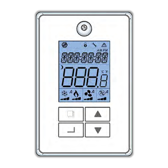
The A indicates that the cooling function is in Automatic mode The flame indicates that heating process is on and working The segmented bar indicates whether the heating is at 33, 66 or 100% output capacity The A indicates that the heating function is in Automatic mode www.lynxspring.com... -
Page 14: Using The Menus
Access any configuration menu by pressing on the menu’ s display screen, Using the and the button, adjust each digit to the desired value. When done, press once more to confirm the new value. Accept to SAVE by selecting YES and pressing www.lynxspring.com... -
Page 15: Quick Setup Menu
When the value is as wanted, press to save the settings and switch to the next object To exit SETUP menu, scroll to the QUIT menu using Press when YES is displayed MSV52 BV75 MSV15 MSV58 MSV55 MSV54 MSV46 BV51 MSV48 MSV47 www.lynxspring.com... - Page 16 See cooling with reheat sequence below See heating with reheat sequence below operation of the controller. System Heat-Rt See cooling / heating sequence below modes (MSV16) not supported will Cl-Ht be rejected Cl-Ht-R See cooling / heating with reheat sequence below www.lynxspring.com...
- Page 17 Sets output BO4 to follow the local occupancy mode when fan is On Occ=Closed Fan-NO Sets output BO4 to follow the local occupancy mode when fan is On Occ=Opened Fan-NC Network Sets the device output BO4 to follow object BV14 Aux_cmd www.lynxspring.com...
- Page 18 Sets the configuration of AI3 to use a remote Normally Cool ChangeOverContact for a 2 pipes system COC/NC Sets the configuration of AI3 to use a remote 10K changeover sensor for a 2 pipes system via AV13 object Sets the configuration of AI3 to use a remote monitoring 10K sensor via AV12 object www.lynxspring.com...
-
Page 19: Applications, Sequences And Curves
PIDZoneCool(Loop1) relates to Cooling demand(AV22) 6°F (2.8°C) 7°F (3.3°C) 8°F (3.9°C) Reverse Direct 9°F (5.0°C) Action Action 10°F (5.6°C) °C °C Deadband Default : 5°F (2.2°C) 1°C..2.5°C SetpointDB - AV63 Min: 2°F (1°C) Max: 5°F (2.5°C) Default : Min: 2°F (1°C) www.lynxspring.com... -
Page 20: 4 Pipes - Modulating 0-10 Vdc Valves
Add 24VAC transformer when the power is not supplied by the equipment On a call for cooling: Cooling valve will modulate to maintain room temperature. Heating valve is closed. On a call for heat: Heating valve will modulate to maintain room temperature. Cooling valve is closed. www.lynxspring.com... -
Page 21: Pipes Modulating Floating Valves
Add 24VAC transformer when the power is not supplied by the equipment On a call for cooling: Cooling valve will modulate to maintain room temperature. Heating valve is closed. On a call for heat: Heating valve will modulate to maintain room temperature. Cooling valve is closed. www.lynxspring.com... -
Page 22: 4 Pipes - On/Off N.c. Valves
Add 24VAC transformer when the power is not supplied by the equipment On a call for cooling: Cooling valve will open to maintain room temperature. Heating valve is closed. On a call for heat: Heating valve will open to maintain room temperature. Cooling valve is closed. www.lynxspring.com... -
Page 23: 4 Pipes - On/Off N.o. Valves
Add 24VAC transformer when the power is not supplied by the equipment On a call for cooling: Cooling valve will open to maintain room temperature. Heating valve is closed. On a call for heat: Heating valve will open to maintain room temperature. Cooling valve is closed. www.lynxspring.com... -
Page 24: Pipes Modulating 0-10 Vdc Valves
On a call for cooling: If the supply water temperature is less than 17.0°C (63F). Cooling valve will modulate to maintain room temperature. by the equipment Heating valve is closed. On a call for heat: If the supply water temperature is greater than 18.5°C (65F). Heating valve will modulate to maintain room temperature. Cooling valve is closed. www.lynxspring.com... -
Page 25: Pipes Modulating Floating Valves
On a call for cooling: If the supply water temperature is less than 17.0°C (63F). Cooling valve will modulate to maintain room temperature. by the equipment Heating valve is closed. On a call for heat: If the supply water temperature is greater than 18.5°C (65F). Heating valve will modulate to maintain room temperature. Cooling valve is closed. www.lynxspring.com... -
Page 26: Pipes On/Off N.o. Valves
On a call for cooling: If the supply water temperature is less than 17.0°C (63F). Cooling valve will open to maintain room temperature. Heating valve is closed. On a call for heat: If the supply water temperature is greater than 18.5°C (65F). Heating valve will open to maintain room temperature. Cooling valve is closed. www.lynxspring.com... - Page 27 On a call for cooling: If the supply water temperature is less than 17.0°C (63F). Cooling valve will open to maintain room temperature. Heating valve is closed. On a call for heat: If the supply water temperature is greater than 18.5°C (65F). Heating valve will open to maintain room temperature. Cooling valve is closed. www.lynxspring.com...
-
Page 28: Single Speed Analog Fan Control
(Keepfan BV66) = FanOff will shuts down the fan completely. by the equipment Stand-by & Unoccupied Mode: Fan will always operate in Auto mode during Stand-by or Unoccupied periods www.lynxspring.com... - Page 29 In the controller deadband between heating and cooling setpoints Autodemand (Keepfan BV66) = FanLow allows the fan to stay at Low fan speed and (Keepfan BV66) = FanOff will shuts down the fan completely. Stand-by & Unoccupied Mode: Fan will always operate in Auto mode during Stand-by or Unoccupied periods www.lynxspring.com...
- Page 30 In the controller deadband between heating and cooling setpoints Autodemand (Keepfan BV66) = FanLow allows the by the equipment fan to stay at Low fan speed and (Keepfan BV66) = FanOff will shuts down the fan completely. Stand-by & Unoccupied Mode: Fan will always operate in Auto mode during Stand-by or Unoccupied periods www.lynxspring.com...
-
Page 31: Single Speed On/Off Fan Control
ON and (Keepfan BV66) = FanOff will shuts down the fan completely. NONE Control MS/TP Stand-by & Unoccupied Mode: Fan will always operate in Auto mode during Stand-by or Unoccupied periods Fan – Single speed Add 24VAC transformer when the power is not supplied by the equipment www.lynxspring.com... -
Page 32: Reheat Control
FCU is hot water water *RS : Room Sensor Add 24VAC transformer when the power is not supplied A typical reheat device in some area used in conjunction with an FCU can even be a separate baseboard heating unit by the equipment www.lynxspring.com... - Page 33 *RS : Room Sensor is hot water water Add 24VAC transformer when the power is not supplied by the equipment A typical reheat device in some area used in conjunction with an FCU can even be a separate baseboard heating unit www.lynxspring.com...
-
Page 34: Service Menu
3 seconds to access the QUIT screen Using the press when “YES” is displayed Notes: Please refer to the object list tables below for a reference on each objects and their available selection The typical priority set at stage is ‘’Normal’’ www.lynxspring.com... -
Page 35: Test Io Menu
To exit TEST IO MODE, scroll to the QUIT menu using Using the , press when “YES” is displayed Notes: Exiting the Test IO mode will revert the controller to its normal state of operation as per the configuration used www.lynxspring.com... -
Page 36: Object List
• Cfg: represent configuration properties of the device that are typically only set once during commissioning and start-up • User: represent properties or objects that are typically manipulated by users of the controller www.lynxspring.com • Status: represent objects or properties that are ‘’typically’’ meant to be displayed on graphics for various required visualization... -
Page 37: Analog Values
• Cfg: represent configuration properties of the device that are typically only set once during commissioning and start-up • User: represent properties or objects that are typically manipulated by users of the controller www.lynxspring.com • Status: represent objects or properties that are ‘’typically’’ meant to be displayed on graphics for various required visualization... -
Page 38: Binary Values
• User: represent properties or objects that are typically manipulated by users of the controller • Status: represent objects or properties that are ‘’typically’’ meant to be displayed on graphics for various required visualization www.lynxspring.com • Cmd: represent objects that can be controlled directly by other BACnet external process... -
Page 39: Multistates Values
• Cfg: represent configuration properties of the device that are typically only set once during commissioning and start-up • User: represent properties or objects that are typically manipulated by users of the controller www.lynxspring.com • Status: represent objects or properties that are ‘’typically’’ meant to be displayed on graphics for various required visualization... - Page 40 • Cfg: represent configuration properties of the device that are typically only set once during commissioning and start-up • User: represent properties or objects that are typically manipulated by users of the controller www.lynxspring.com • Status: represent objects or properties that are ‘’typically’’ meant to be displayed on graphics for various required visualization...
- Page 41 • Cfg: represent configuration properties of the device that are typically only set once during commissioning and start-up • User: represent properties or objects that are typically manipulated by users of the controller www.lynxspring.com • Status: represent objects or properties that are ‘’typically’’ meant to be displayed on graphics for various required visualization...
- Page 42 • Cfg: represent configuration properties of the device that are typically only set once during commissioning and start-up • User: represent properties or objects that are typically manipulated by users of the controller www.lynxspring.com • Status: represent objects or properties that are ‘’typically’’ meant to be displayed on graphics for various required visualization...
-
Page 43: Rs485 Network Guidelines
RS485 Network Guidelines www.lynxspring.com... - Page 44 RS485 Network Guidelines www.lynxspring.com...
- Page 45 RS485 Network Guidelines www.lynxspring.com...
- Page 46 RS485 Network Guidelines www.lynxspring.com...
- Page 47 RS485 Network Guidelines www.lynxspring.com...
-
Page 48: Specifications
Technical Specifications (USB-485 Cable Adapter) Onyxx LX UI Software www.lynxspring.com...
Need help?
Do you have a question about the BW437-FCU-LX and is the answer not in the manual?
Questions and answers