Table of Contents
Advertisement
Quick Links
:
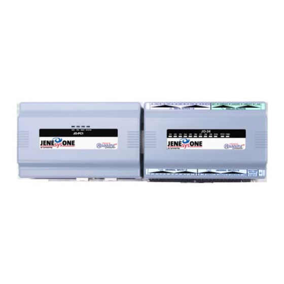
This document covers the mounting and wiring of the
™
JENEsysONE
equipment controller JO-PC1 base
controller. It assumes that you are an engineer, technician,
or service person who is performing control system
installation. Instructions in this document apply to the
following products:
Models
Description
JO-PC1
JO-PC1 base unit controller
JO-34
JO-34 base 34 point I/O module
JO-16
JO-16 optional 16 point I/O module
Not covered in this document is the Niagara
Note
fully functioning unit. This includes setting host IP address and password, serial port configuration, and
other parameters. Refer to the JENE NiagaraAX Install and Startup Guide for this information.
In addition, the mounting and wiring of JENEsysONE
documents. See sections
These are the main topics included in this document:
Preparation,
page 2
•
Precautions,
page 3
•
Mounting,
page 5
•
Board Layout,
page 7
•
About Expansion Options,
•
Wiring Details,
page 10
•
Grounding,
page 10
–
Power Wiring,
–
Communications Wiring,
–
RS-485 Biasing,
–
Power Wiring,
page 11
•
Using Status LEDs,
•
Maintaining the JO-PC1,
•
Replacement Parts,
•
Certifications,
page 24
•
Tab Mounting Dimensions,
•
JENEsysONE and ProBuilder are trademarks and JENEsys is a registered trademark of Lynxspring, Inc.
Niagara Framework, Niagara AX Framework and the Sedona Framework are trademarks of Tridium, Inc.
JO-PC1 Base Controller Mounting and Wiring Guide
Part Number JO-PC1 rev 1
MOUNTING AND WIRING GUIDE
"Related Documentation,"
page 8
page 11
page 11
page 13
page 19
page 20
page 21
page 26
Updated: January 16, 2012
JO-PC1 Base Controller
JENEsysONE™ Equipment Controller
AX
software installation and configuration required for a
®
expansion options are covered in separate
page 4, and
"About Expansion Options,"
page 8.
1
Advertisement
Table of Contents

Subscribe to Our Youtube Channel
Related Manuals for Lynxspring JENEsysONE JO-PC1


Summary of Contents for Lynxspring JENEsysONE JO-PC1
- Page 1 Tab Mounting Dimensions, page 26 • JENEsysONE and ProBuilder are trademarks and JENEsys is a registered trademark of Lynxspring, Inc. Niagara Framework, Niagara AX Framework and the Sedona Framework are trademarks of Tridium, Inc. JO-PC1 Base Controller Mounting and Wiring Guide...
-
Page 2: Included In This Package
Preparation Included in this Package Preparation Unpack the JO-PC1 and inspect the package contents for damaged or missing components. If damaged, notify the appropriate carrier at once and return any damaged components for immediate repair or replacement. See “Returning a Defective Unit” on page 23. -
Page 3: Safety Precautions
Precautions Safety Precautions Precautions This document uses the following warning and caution conventions: Cautions remind the reader to be careful. They alert readers to situations where there is a chance Caution that the reader might perform an action that cannot be undone, might receive unexpected results, or might lose data. -
Page 4: Battery Precautions
To properly dispose of this product, please take it to a local recycling center. If a local recycling center cannot be found, please return it to one of these offices: Lynxspring, Inc. 1210 NE Windsor Drive... -
Page 5: Environmental Requirements
Mounting Environmental Requirements Mounting Mount the JO-PC1 controller in a location that allows clearance for wiring, servicing, and module removal. Environmental Requirements Note the following requirements for the controller’s mounting location: This product is intended for indoor use only. Do not expose the unit to ambient conditions outside of the •... -
Page 6: Removing And Replacing The Cover
Mounting Removing and Replacing the Cover Figure 1 JO-PC1 controller and accessory mounting details Mounting on DIN Rail Removing from DIN Rail DIN rail End Clip JO-34 JO-PC1 Install DIN rail End Clip DIN Rail (Stop Clip) at both ends End Clip of final assembly. -
Page 7: Board Layout
Board Layout Removing and Replacing the Cover Figure 2 Press in four tabs on ends of cover to remove cover. Cover Cover Tabs lifted (2 each end) away Press Tabs In If accessory modules are plugged into the controller, you may need to slide them away from the unit to Note get to the cover tabs. -
Page 8: About Expansion Options
About Expansion Options About Option Cards About Expansion Options The JO-PC1 controller provides for field-installable expansion with two kinds of options: Option cards—Install on connectors inside the controller base unit. See “About Option Cards”. • Accessory modules—To “chain” on the JO-PC1’s 20-pin end connector. See “About Accessory •... -
Page 9: Mounting Option Cards
About Expansion Options About Accessory Modules Mounting Option Cards Refer to the installation document that accompanies a specific option card for complete details. The following procedure provides a basic set of steps. Procedure 2 Mounting option cards on a JO-PC1 controller. Remove power from the controller—see the previous Warning. -
Page 10: Wiring Details
Wiring Details Grounding Each accessory module has a DIN-mount base, and typically provides two (2) 20-pin connectors that allow you to “chain” multiple accessories (see Procedure 1 on page 5). Table 2 lists currently available accessory modules. Table 2 JO-PC1 accessory modules. Model Description Notes... -
Page 11: Power Wiring
Wiring Details Power Wiring Power is provided for plug-in accessory modules through the 20-pin accessory connectors. However, you should also connect the earth ground spade lug of each accessory module to ground in the same manner. Figure 4 IO-34 power wiring and earth ground connections. JO-PC1 JO-34 Earth Ground... - Page 12 Wiring Details Communications Wiring Prior to connecting cables, provide strain relief for them to prevent damage to the controller. Note Figure 5 JO-PC1 controller bottom side (cover removed). Ethernet (RJ-45) Primary Ethernet (RJ-45) LAN 1 LAN 2 Battery in bracket (on top of option cards, if any) 20 Pin...
-
Page 13: Rs-485 Biasing
Wiring Details RS-485 Biasing If a modem option card (JENE-PC-MODEM) is installed, this port becomes disabled—except if Note rebooted with the mode jumper (see Figure 3 on page 7) in the “Serial Shell” position. Table 3 Serial port (RS-232 and RS-485) pinouts. Base RS-232 DB-9 Port (COM1) Base RS-485 Port (COM2) Pinout References... -
Page 14: Adding Rs-485 Bias
Wiring Details RS-485 Biasing from RS-485 “-” to Ground. • In general, only one device on an RS-485 trunk should be biased. Otherwise, undue loading of the Notes • circuit may result, with fewer devices supported. RS-485 bias resistors are different than “termination resistors”, externally installed at the two •... - Page 15 Wiring Details RS-485 Biasing Figure 6 Basic stages of controller disassembly. Cover removed, reveals metal shield Philips head screws Metal shield lifted away NPM board Metal standoffs NPM board lifted away Jumper block for RS-485 biasing Procedure 3 Disassembling the controller. Remove all power from the controller.
- Page 16 Wiring Details RS-485 Biasing Procedure 4 Installing shorting blocks to add RS-485 biasing. Locate the four jumper pins behind the RS-485 port. Step 1 Newer units have two 2-pin shorting blocks pre-installed on one pin each. See Figure To add biasing, install a shorting block across both pins on each side of the jumper block, shorting the Step 2 pins as shown in Figure 7...
-
Page 17: Power Up And Initial Checkout
Power Up and Initial Checkout Connect the Backup Battery Power Up and Initial Checkout Ensure power wiring to the JO-PC1 controller is ready—see the “Power Wiring” section on page 11. Refer to Figure 3 on page 7 for the locations of the JO-PC1 battery connector, and status LEDs. Following all mounting and wiring, perform the following: Procedure 6 Initial power up and checkout... -
Page 18: About The Battery
Power Up and Initial Checkout About the Battery About the Battery The JO-PC1 is provided with a custom 10-cell NiMH battery pack mounted to the unit (under the cover). This battery allows the JACE to continue operation through very short power bumps (a few seconds in duration). If a longer power outage occurs, the battery provides enough run time for the JO-PC1 to backup data and then shutdown. -
Page 19: Using Status Leds
Using Status LEDs Ethernet Ports Using Status LEDs The JO-PC1 controller includes several LEDs that can help determine the status of the unit. They are located in two places: the top of the controller (visible through the cover), and for serial ports, on the bottom board (only with cover removed). -
Page 20: Required Battery Maintenance
Maintaining the JO-PC1 Cleaning Maintaining the JO-PC1 This section provides information on the following topics: Cleaning • Required Battery Maintenance • Replacement Parts • Replacing the JO-PC1 base assembly • Returning a Defective Unit • Cleaning If dust or metal filings are present inside the unit, clean with vacuum or compressed air. Otherwise, no cleaning inside the unit is required. -
Page 21: Non-Replaceable Parts
Replacement Parts Non-replaceable Parts Remove the old battery and bracket assembly by taking out the four screws holding it in place, setting Step 4 the screws aside for later. Unplug the battery from the connector on the base board. Plug the battery connector plug of the replacement battery into the battery connector on the controller. Step 5 Set the replacement battery/bracket assembly back over the option card slots, with the mounting holes Step 6... -
Page 22: New Replacement Units
Replacement Parts New Replacement Units New Replacement Units To replace a faulty unit, order and install a new JO-PC1 controller—please note this series of products does not have special “field replacement units,” or FRUs, with separate part numbers. If the faulty JO-PC1 is still in warranty, you can receive credit by returning it. Be sure to contact the vendor for a return material authorization (RMA) number before shipping an item for return credit. -
Page 23: Returning A Defective Unit
Replacement Parts Returning a Defective Unit In this case: Making a careful note or all wiring terminations, unplug the I/O connector plugs and earth ground wires from the installed IO modules. Remove the installed accessory modules, starting with the end module. Modules may be secured by screws in mounting tabs or clipped to a DIN rail, or fastened by some combination. -
Page 24: Federal Communications Commission (Fcc)
Certifications Federal Communications Commission (FCC) Certifications Federal Communications Commission (FCC) This equipment generates, uses, and can radiate radio frequency energy, and if not installed and used in accordance with the instruction manual, may cause interference with radio communications. It has been tested and found to comply with the limits for a Class A computing device pursuant to Subpart J of Part 15 of FCC Rules, which are designed to provide reasonable protection against such interference when operated in a commercial environment. -
Page 25: Ce Declaration Of Conformity
* Note 1, A ferrite (Fair-Rite part #043‘‘64181) was placed around a shielded power cord. Information and/or specifications published here are current as of the date of publication of this document. Lynxspring, Inc. reserves the right to change or modify specifications without prior notice. -
Page 26: Tab Mounting Dimensions
Tab Mounting Dimensions 0.170” Dia. 6.719” (170.66mm) (4.32mm) JO-PC1 3.75” (95.25mm) Note: Electronic and printed versions of this 2.50” guide may not show the dimensions to scale. 4.00” (63.50mm) (101.6mm) Verify all measurements before drilling. DIN mounting is recommended over tab mounting. Figure 1 on page 6.
Need help?
Do you have a question about the JENEsysONE JO-PC1 and is the answer not in the manual?
Questions and answers