
Related Manuals for Future Automation SPS1300


Summary of Contents for Future Automation SPS1300
- Page 1 SPS80 0/ 1 2 0 0 /1 3 0 0 S LI DI NG PA N E L SY ST E M & S C REEN A DV A NCE / S C R E E N A D V A N C E H EA V Y I N S TA L LA T I O N I N ST R U CTI ON S I SSUE 016...
-
Page 3: Sa Fety Di Sc La Imer
Clean only with a dry cloth and always unplug any electrical items being used in conjunction with this product before cleaning. Future Sound & Vision trading as Future Automation intend to make this and all documentation as accurate as possible. However, Future Automation makes no claim that the information contained herein covers all details, conditions or variations, nor does it provide for every possible contingency in connection with the installation or use of this product. - Page 4 Under the warranty, Future Automation aims to either solve the issue remotely (via telephone or email support) or if the mechanism requires a part, arrange a visit to your premises by a Future Automation approved engineer or send replacement items where appropriate.
-
Page 5: Gui D E C O Nt E Nts
GUI D E C O NT E NTS SAFE TY DISCLA IM ER PR OD UCT WA RR A NT Y & RISK ASSESS M EN T GUIDE C ONT ENTS PACKA GE CONTENT S MECH ANISM QUICK-ST A RT GUI D E MECH ANISM PRE TEST ING SCRE EN POSITIONING PANEL MECH ANISM INSTA LLA TIO N... -
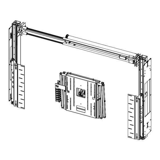
Page 6: Package Contents
PACKAG E CONT ENTS 1 - SA/SAH OPTION & SPS MECHANISM 1.1 - PANEL MECHANISM RIGHT 1.2 - PANEL MECHANISM LEFT 1.3 - PANEL DRIVE UNIT 1.4 - SCREEN ADVANCE UNIT 1.5 - SCREEN ADVANCE UNIT HEAVY 1.6 - PANEL MOUNT PLATES 2 - CONTROL BOX 3 - IR REMOTE CONTROL ITEMS NOT SHOWN ON PAGE... - Page 7 MEC HA NI SM QUI CK - S TART GUI DE Some Future Automation mechanisms may ship with the control box disconnected to prevent damage during transit. In order to operate the mechanism, the control box will need to reconnected, then have mains power applied along with the desired control method.
- Page 8 (M5 x 35mm bolts connect them) Panel Drive Unit cams are factory set to the correct positions and should not be adjusted without first contacting a member of the Future Automation team.
-
Page 9: Screen Pos I Tioning
SCREEN POS I TIONING Enclosure height should accommodate height of screen and height of sliding panel. Ensure cabinet dimensions are correct. Refer to the technical sheet for correct dimensions. Mark up the top position of the screen inside the enclosure along with a center line in preparation for display positioning. - Page 10 P AN EL ME CH AN IS M Mounting plates will need to be installed perfectly level and in the IN S T A L L A TI ON DOWN position before proceeding Offer Side up to the inside of enclosure and position so the Panel Mount are central in relation to the screen centre height marked previously.
- Page 11 DRI V E U NI T INS T A L LA TI ON Locate Panel Drive Unit and insert motor end of the unit to the two couplers at the top of the right hand panel. T e l es co pic M 8 Lock ing Bolt Loosen the M8 locking bolt...
- Page 12 SCR EEN ADVAN CE P OS I T I ONI N G (SA) Offer display to Screen Advance mechanism. Measure from the top of the display to the key-hole mount slot. The measurement taken can be used to correctly position mechanism inside the enclosure.
- Page 13 SC RE EN AD VA N CE M O U NTIN G (S A) Fix a screw into the wall with the head Remove the Screen Mount Plate by protruding at marked position, so that loosening the two Screen Mounting the SA can be freely supported inside Toggles and lifting up and away.
- Page 14 SETT IN G THE MEC HANI SM OU T POSITION S (S A) To alter the OUT position of the screen advance, press the OUT button followed by the STOP button when the screen is at the desired position. Press STORE, followed by OUT to set this position as the new OUT position.
- Page 15 SCR EEN ADVAN CE M O U NT ING (SA H) Offer display to Screen Advance Heavy (SAH) mechanism. Measure from the top of the display to the two largest mounting holes on the SAH Bracket Wall Plate. The measurement taken can be used to correctly position mechanism inside the enclosure.
- Page 16 SCR EEN ADVAN CE M O U NT ING (SA H) Remove the two Uprights from the SAH and attach them to the display using the supplied fixings. Using the previous measurement for reference, secure the SAH mechanism into the enclosure using the appropriate fixings (NOT INCLUDED) Confirm that the mechanism is level and in the correct position.
- Page 17 SET T I N G TH E M E C HAN ISM IN / O U T PO SI TI ON S (S AH) To alter the OUT position of the screen advance heavy, press the OUT button followed by the STOP button when the screen is at the desired position.
-
Page 18: Con N E C Tionw I R Ing
CON N E C TION W I R ING Connect the Drive Unit to the Side Panels Each mechanism has its own set of using the 9 pin AMP plugs together wires that are control box inserts and (Labelled A to A) block connectors. - Page 19 P ANEL MOUNT PLATE FITT IN G The front mounting plates hold your concealment panel onto the mechanism. It is attached to the runners with M6 x 10mm CSK bolts with washers. Use one fixing in each slot at one of the three mounting heights available.
- Page 20 EN C LO SURE P AN E L MOUNT IN G (Clearance) Remove the mounting plates from the mechanism to attach the enclosure panel. Use the previous measurement as a guide to attach the mounting plates to the enclosure panel leaving 5mm of clearance around the perimeter of the panel.
- Page 21 P AN EL UP POSI TI ON ADJU S T MEN T Loosen the two bolts shown in the detail view. Do not fully remove them. Slide the switch plate up will make the panel travel higher. Sliding the plate down will make the plate travel less.
-
Page 22: Position Adjustment
P AN EL DOWN P OS I T I ON ADJ USTME NT The down position can be adjusted by moving the position of the mount plate in the slots on the mechanism. (Right) There is 60mm (2.4”) of travel within this slot. - Page 23 D ISP LA Y F ITTING Return the mechanism from service mode by pressing ‘A’ repeatedly on the IR remote. Once the mechanism cannot pulse any further, wait 2 seconds and the mechanism will return to user mode. The mechanism should be fully extended before the screen can be fitted.
- Page 24 REPLACING MECHANISM BATTERIES The standard Future Automation Infrared (IR) remote control required x2 AAA batteries to operate. These are provided with the mechanism in the Accessories Pack. These batteries can be replaced as the per the image below.
- Page 25 INF RA RE D (I R) This mechanism can be controlled via the supplied 14 button Infrared (IR) Remote Control, paired with the supplied Infrared (IR) lead and sensor. The mechanism's functions can be controlled by plugging the Infrared (IR) lead and sensor into the 3.5mm IR Input Jack shown on the General Mechanism Control page.
-
Page 26: Radio Frequency
RA DIO FREQUE NCY ( RF) If purchased with the Radio Frequency (RF) control option, this mechanism can be controlled via the supplied 4 button Radio Frequency (RF) Remote Control, paired with the in-built Radio Frequency (RF) sensor. Confirmation of Radio Frequency (RF) input will be shown by a single flash of the large green LED located on the end of the control box. -
Page 27: Con T Ac Tclos U Re
CON T AC T CLOS U RE This Mechanism can be controlled via Contact Closure, utilising an 8 Pin RJ45 Connector attached to a length of CAT5 (Type 568A or 568B) cable. The mechanism’s functions can be controlled by plugging this into the RJ45 port on the mechanism control board, then shorting pins 1-8 on this connector as shown in the Contact Closure Input Table below. - Page 28 RS2 32 CON T RO L This Mechanism can be controlled via RS232, utilising a 6 Pin RJ11/RJ25 connector OR 9 Pin Serial connector attached to a length of 6 core cable. The mechanism's functions can be controlled by plugging this into the RJ11/RJ25 port on the mechanism control box, then inputting the RS232 commands shown in the RS232 Input Table below.
- Page 29 NO T E S :...
- Page 30 EUROPEAN OFFICE NORTH AMERICAN OFFICE Address: Address: Unit 6-8 Enterprise Park Brunel Road 127 Venture Drive Bedford Dover Bedfordshire MK41 9TG 03820 Phone: +44 (0) 1438 833577 Phone: +1 (603) 742 9181 Email: info@futureautomation.co.uk Email: info@futureautomation.net Office Hours: Office Hours: Mon - Fri 8:00 to 17:30 GMT Mon - Fri 7:00 to 17:00 EST Saturday &...
Need help?
Do you have a question about the SPS1300 and is the answer not in the manual?
Questions and answers