
Related Manuals for Future Automation PICSIDE


Summary of Contents for Future Automation PICSIDE
- Page 1 PICS ID E PI C S I D E1 , PIC SI D E 2, PI CS I D E 3 S I D E M O VI N G PI C TU RE ME CH A N I SM I NST ALLA T I ON I N ST R U C T I O N S I S S UE 003...
-
Page 3: Safety Dis Claimer
Clean only with a dry cloth and always unplug any electrical items being used in conjunction with this product before cleaning. Future Sound & Vision trading as Future Automation intend to make this and all documentation as accurate as possible. However, Future Automation makes no claim that the information contained herein covers all details, conditions or variations, nor does it provide for every possible contingency in connection with the installation or use of this product. - Page 4 Under the warranty, Future Automation aims to either solve the issue remotely (via telephone or email support) or if the mechanism requires a part, arrange a visit to your premises by a Future Automation approved engineer or send replacement items where appropriate.
- Page 5 G UID E C ON TEN T S S AF ET Y D I S C L A I M ER P ROD UC T W A R R A NT Y & R I S K AS S E SS ME N T G U I DE C ON TE NT S P ACKA G E C O NT E NT S M E CHA NI S M Q U I C K - S T A R T GU I D E...
-
Page 6: Package Contents
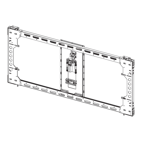
1.6 - X8 MOVING PANEL BRACKETS 2 - CONTROL BOX 3 - IR REMOTE CONTROL ITEMS NOT SHOWN ON PAGE PICSIDE ACCESSORY PACK: - 2X AAA BATTERIES - 6X M6 NUTS AND BOLTS - MAINS POWER, IR AND CONTACT CLOSURE LEADS... - Page 7 QU ICK -ST A RT G U I DE Some Future Automation mechanisms may ship with the control box disconnected to prevent damage during transit. In order to operate the mechanism, the control box will need to reconnected, then have mains power applied along with the desired control method.
- Page 8 MEC HA NI SM P R E TES TIN G Before installing your mechanism, it is important that you perform the following checks. • The product is in good condition • There is no damage to any parts of the mechanism •...
- Page 9 MECHANISM MOUNT ING Offer the mechanism to the wall so that it aligns with the previously marked points. Use appropriate fixings to secure the mechanism to the wall. Run mechanism power cables through the cable entry/exit cavity in the wall. Use spirit level to confirm that mechanism is level...
- Page 10 MEC HA NI SM M OU NTI NG CON T . Insert a minimum of 6 fixings into the slots to secure the mechanism to the wall. Move the frame left to right to gain access to the top and bottom mounting slots.
- Page 11 P I CT U RE M O UN T ING Attach brackets to inside upper edge of canvas using the included fixings. 10mm Adjust height of bolts in top of mechanism so that the canvas has at least 10mm of clearance behind it.
- Page 12 S T O P POS I TI ON ADJUS TMENT To alter the stopping positions of the mechanism loosen the two bolts shown below on both the left and right sides of the frame. Move the bracket left or right to determine the finish positions and re-tighten bolts.
-
Page 13: Final Checks
FI NAL CHE CKS Make sure the mechanism is fixed securely on the wall and that there are no objects obstructing the path of the mechanism. Test the mechanism movement with the canvas in place to see if there are any issues with the movement cycle. -
Page 14: General Control
REPLACING MECHANISM BATTERIES The standard Future Automation Infrared (IR) remote control required x2 AAA batteries to operate. These are provided with the mechanism in the Accessories Pack. These batteries can be replaced as the per the image below. - Page 15 IN FR ARE D ( I R) This mechanism can be controlled via the supplied 14 button Infrared (IR) Remote Control, paired with the supplied Infrared (IR) lead and sensor. The mechanism's functions can be controlled by plugging the Infrared (IR) lead and sensor into the 3.5mm IR Input Jack shown on the General Mechanism Control page.
-
Page 16: Radio Frequency
RADIO FREQUENCY ( R F) If purchased with the Radio Frequency (RF) control option, this mechanism can be controlled via the supplied 4 button Radio Frequency (RF) Remote Control, paired with the in-built Radio Frequency (RF) sensor. Confirmation of Radio Frequency (RF) input will be shown by a single flash of the large green LED located on the end of the control box. - Page 17 C ON TA CT CLOS URE This Mechanism can be controlled via Contact Closure, utilising an 8 Pin RJ45 Connector attached to a length of CAT5 (Type 568A or 568B) cable. The mechanism’s functions can be controlled by plugging this into the RJ45 port on the mechanism control board, then shorting pins 1-8 on this connector as shown in the Contact Closure Input Table below.
- Page 18 RS 23 2 CONTROL This Mechanism can be controlled via RS232, utilising a 6 Pin RJ11/RJ25 connector OR 9 Pin Serial connector attached to a length of 6 core cable. The mechanism's functions can be controlled by plugging this into the RJ11/RJ25 port on the mechanism control box, then inputting the RS232 commands shown in the RS232 Input Table below.
- Page 19 NOT ES :...
- Page 20 EUROPEAN OFFICE NORTH AMERICAN OFFICE Address: Address: Unit 6-8 Enterprise Park Brunel Road 127 Venture Drive Bedford Dover Bedfordshire MK41 9TG 03820 Phone: +44 (0) 1438 833577 Phone: +1 (603) 742 9181 Email: info@futureautomation.co.uk Email: info@futureautomation.net Office Hours: Office Hours: Mon - Fri 8:00 to 17:30 GMT Mon - Fri 7:00 to 17:00 EST Saturday &...
Need help?
Do you have a question about the PICSIDE and is the answer not in the manual?
Questions and answers