Table of Contents
Advertisement
Quick Links
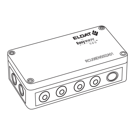
RCU08
Surface-mounted receiver
EN
Models
RCU08EN5002A01
Technical data
Frequency:
868.30 MHz
Modulation:
FSK
Coding:
Easywave neo
Power supply:
230 V AC 50 Hz
Output:
2 potential-free relay
outputs 10 A
1x normally open
contact
1x change-over contact
Input:
2 potential-free button
inputs
Power consumption:
0.9 W standby
2.3 W max. without load
Contact load:
see load table
Degree of protection:
IP66
(in delivery condition)
Operating temperature: -20 °C to +45 °C
Dimensions (W/L/H):
180/94/58 mm
Weight:
447 g
Scope of delivery
RCU08 receiver, operating manual
Load table
Load type
Ohmic load:
Incandescent lamps, 230 V
Halogen lamps, etc.
Inductive load:
Halogen lamps with
wound transformers
(transformer loaded at least
85%)
Non- or series-compensated
fluorescent lamps with
ferromagnetic ballasts
Parallel-compensated
fluorescent lamps with
ferromagnetic ballasts
ECG capacity: electronic
ballasts, electronic
transformers, etc.
Intended use
The device may only be used as a radio receiver
for switching electrical loads according to the load
table. Operation is carried out using Easywave
radio transmitters, an Easywave neo transmitter,
APC01 Easywave neo server or connected but-
tons / switches.
The manufacturer is not liable for damage caused
by improper use or use contrary to the intended
purpose.
Safety instructions
Before operating the device, please read
these instructions carefully! Failure to ob-
serve the instructions may result in fire or
other hazards.
Attention! The device may only
be operated on the 230V/50Hz AC
mains. The electrical installation
may only be carried out by an ap-
proved electrician (according to
VDE 0100).
The device is part of a building installation. Observe
applicable laws, standards and regulations of the coun-
try in which the devices are installed, as well as the
instructions from the manufacturer for the devices to
be switched!
Only load the device up to the specified power limit!
The device must be fused with an upstream 10 A circuit
breaker.
Have non-functioning devices checked by the manu-
facturer and do not make any unauthorised changes
to the device!
Function
The RCU08 receiver is used for potential-free
switching of mains or (protective) low voltage
(SELV) for up to two consumers.
The receiver can be operated in ON/OFF, PULSE
and DEAD MAN operating modes. The ON/OFF
operating mode can also be used with two TIMER
functions and one LOGIC function.
Up to two external buttons can be connected
potential-free to the button inputs of the RCU08
Button inputs
In the factory state, the two external buttons EXT1
and EXT2 use the operating mode ON/OFF (
in 1-button operation. EXT1 is assigned to output
1 (CH1) and EXT2 is assigned to output 2 (CH2).
This assignment is restored after an output or fac-
tory reset.
The factory assignment of the external buttons
can be changed at any time. For this purpose,
the buttons can be programmed or also deleted
in any operating mode of the outputs CH1/CH2,
analogue to radio transmitters.
Max. load
10 A / 2,300 VA
As soon as a button is programmed to an output,
the factory assignment is ignored. If, for example,
the EXT1 button is programmed to output CH2,
it will no longer switch output CH1. If the EXT1
3 A / 690 VA
button is to switch both outputs, it must be pro-
grammed to output CH2 as well as to its originally
assigned output CH1.
External buttons behave like a transmitter button
with the button code B and should always be pro-
3 A / 690 VA
grammed in 1-button operation.
The button inputs have priority over radio trans-
mitters and can therefore be used, for example,
3 A / 690 VA
to temporarily block an output. To do this, connect
a switch and program it into the ON/OFF operat-
ing mode with 2-button operation (
the switch is closed, the respective output also
4 A / 920
VA
remains switched off.
If a switch is programmed in the DEAD MAN op-
erating mode ( ), it switches the output ON as
soon as it is closed. Radio transmitters can switch
the output OFF again at any time.
Setting up the receiver
Installing the receiver ............................... 1
Selecting the location ......................... 1
Mounting the receiver ........................ 1
Electrical connection .......................... 2
Operation ................................................... 2
Operating and indicator elements ...... 2
Operating modes ............................... 3
Conversion table for timer .................. 4
Timer multiplier table.......................... 4
Programming ............................................ 5
Programming transmitters/buttons ..... 5
Adjust the timer...................... ........... 5
Deleting transmitters/buttons ............. 6
Output reset ....................................... 6
Factory reset ...................................... 7
Bidirectional functions ............................. 7
Programming a server ....................... 7
Deleting a server ................................ 7
General information .................................. 8
A
Installing the receiver
A1
Selecting the location
The device is considered to be an electrical
switch according to EN 60669-2-1.
Note that installation in distribution boxes, enclo-
sures made of metal, in the immediate vicinity of
large metal objects, on the floor or near the floor
can have a negative impact on the radio range.
There are no restrictions with regard to the instal-
lation height.
A2
Mounting the receiver
1. Remove the housing cover.
)
2. Attach the receiver to the mounting location.
Use the screw threads of the cover screws for
this purpose.
3. Switch off the supply voltage.
4. Insert the connection cables through the dou-
ble membrane glands. Pull the cable back
briefly to form the seal.
5. Connect the cables for the power supply,
consumers to be switched and, if necessary,
external button according to the connection
diagram (see section A3 "Electrical connec-
tion").
6. Switch on the power supply (230 V AC).
7. Now program the transmitter codes for the
transmitter and, if applicable, the external
buttons on the receiver (see section C1 "Pro-
gram transmitters/buttons").
). As long as
8. Screw the housing cover back onto the lower
part of the housing.
Mains power cables or cables
connected to other circuits must
not be used for the button con-
nections!
The receiver is live during
programming! Do not touch
the terminals; there is a risk of
electric shock!
Advertisement
Table of Contents

Related Manuals for Easy wave RCU08

Summary of Contents for Easy wave RCU08
-
Page 1: Table Of Contents
There are no restrictions with regard to the instal- Up to two external buttons can be connected Power consumption: 0.9 W standby lation height. potential-free to the button inputs of the RCU08 2.3 W max. without load Mounting the receiver Contact load: see load table... -
Page 2: A3 Electrical Connection
Installing the receiver Electrical connection Cable cross-sections Power supply and connection cables (X1-X3): rigid cables: 0.5 - 2.5 mm² CH1 CH2 flexible cables with wire end ferrule: 0.5 - 1.5 mm² Up to two wires with max. 2.5 mm² can be µ... -
Page 3: B2 Operating Modes
Operation Operating modes By pressing the P button, you first determine In 2-button operation (2TB), the transmitter but- triggering a PULSE. tons A or C are for switching ON, starting the TIM- whether you want to program a transmitter/button Each button can be used to start and retrigger the in 2-button operation or in 1-button operation . -
Page 4: B3 Conversion Table For Timer
Operation Conversion table for TIMER adjustable Conversion seconds with multiplier in time (hours:minutes:seconds) Multiplier Multiplier Seconds Counter 1000 Seconds Counter 1000 0:00:01 0:00:10 0:01:40 0:16:40 0:00:31 0:05:10 0:51:40 8:36:40 0:00:02 0:00:20 0:03:20 0:33:20 0:00:32 0:05:20 0:53:20 8:53:20 0:00:03 0:00:30 0:05:00 0:50:00 0:00:33 0:05:30... -
Page 5: C Programming
1x briefly Timeout: If no buttons are pressed within 30 seconds, the RCU08 automatically switches back to operating mode. The settings are not saved. Programming can be cancelled by pressing the P button several times. -
Page 6: C3 Deleting Transmitters/Buttons
TIMER reset. When all the LEDs turn off, the receiver is CH1 CH2 ready for operation. 1) If no buttons are pressed within 30 seconds, the RCU08 automatically switches back to operating mode. The settings are not saved. > >... -
Page 7: C5 Factory Reset
An incoming switch command via the server is a server. The RCU08 is automatically recognised and con- shown as a dash (-) on the display of the RCU08. figured by the server as a 2-fold switch receiver. Program the APC01 server according to the in- structions in the Easywave app. -
Page 8: E General Information
Conformity ELDAT EaS GmbH hereby declares that the radio equipment type RCU08 is in compliance with the Directive 2014/53/EU. The full text of the EU declaration of conformity can be obtained at the following internet address: www.eldat.de...
Need help?
Do you have a question about the RCU08 and is the answer not in the manual?
Questions and answers