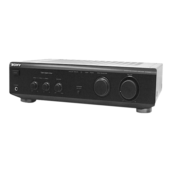
Sony TA-FE210 Service Manual
Integrated stereo amplifier
Hide thumbs
Also See for TA-FE210:
- Operating instructions manual (48 pages) ,
- Service manual (10 pages)
Advertisement
Quick Links
TA-FE210
SERVICE MANUAL
AEP Model
UK Model
The TA-FE210 is respectively the TA-FE200 model whose panels
have been changed.
This service manual describes only the difference of exploded
views, schematic diagram, printed wiring boards and electrical
parts list.
For the other information, refer to the service manual for TA-FE200
(9-960-697-ππ) previously issued.
INTEGRATED STEREO AMPLIFIER
MICROFILM
– 1 –
Advertisement

Subscribe to Our Youtube Channel
Related Manuals for Sony TA-FE210


Summary of Contents for Sony TA-FE210
- Page 1 TA-FE210 SERVICE MANUAL AEP Model UK Model The TA-FE210 is respectively the TA-FE200 model whose panels have been changed. This service manual describes only the difference of exploded views, schematic diagram, printed wiring boards and electrical parts list. For the other information, refer to the service manual for TA-FE200 (9-960-697-ππ) previously issued.
- Page 2 1. DIFFERENCE OF EXPLODED VIEWS, AND CORRECTION : Corrected portion Page TA-FE200 TA-FE210 Ref. No. Part No. Description Remark Part No. Description Remark X-4946-799-3 PANEL ASSY, FRONT X-4948-265-1 PANEL ASSY, FRONT 1-659-952-11 AC SW BOARD * 1-659-952-11 AC SW BOARD...
- Page 3 – 3 –...
-
Page 6: Electrical Parts List
AC IN AC SW CN DC CONTROL 5. ELECTRICAL PARTS LIST NOTE: The components identified by mark • Due to standardization, replacements in • Items marked “*” are not stocked since ! or dotted line with mark. ! are the parts list may be different from the they are seldom required for routine service. - Page 7 CONTROL HEADPHONE MAIN Ref. No. Part No. Description Remark Ref. No. Part No. Description Remark RV204 1-223-397-11 RES, VAR, CARBON 100K/100K (TREBLE) C361 1-136-495-11 FILM 0.068uF C362 1-136-495-11 FILM 0.068uF < SWITCH > C363 1-126-967-11 ELECT 47uF C364 1-162-195-31 CERAMIC 4.7PF S201 1-571-112-21 SWITCH, PUSH (1 KEY) (LOUDNESS)
- Page 8 MAIN Ref. No. Part No. Description Remark Ref. No. Part No. Description Remark < COIL > R301 1-249-439-11 CARBON 1/4W R302 1-249-417-11 CARBON 1/4W L301 1-420-872-00 COIL, AIR-CORE R303 1-249-415-11 CARBON 1/4W L351 1-420-872-00 COIL, AIR-CORE R304 1-249-439-11 CARBON 1/4W R305 1-249-421-11 CARBON 2.2K...
- Page 9 TA-FE210 MAIN Ref. No. Part No. Description Remark R903 1-247-750-11 CARBON 1/2W R904 1-247-750-11 CARBON 1/2W R905 1-247-750-11 CARBON 1/2W R907 1-247-752-11 CARBON 1/2W R908 1-247-752-11 CARBON 1/2W R910 1-249-429-11 CARBON 1/4W R912 1-249-429-11 CARBON 1/4W R913 1-249-433-11 CARBON 1/4W <...
- Page 10 3. SCHEMATIC DIAGRAM 4. PRINTED WIRING BOARDS • IC Block Diagrams IC103 LC7818 IC601 µPC1237HA TA-FE210 TA-FE210 TA-FE210 • Semiconductor Location Ref. No. Location Ref. No. Location TA-FE210 D301 IC102 IC103 D302 D351 IC301 F-10 TA-FE210 D352 IC601 D601 D701...
Need help?
Do you have a question about the TA-FE210 and is the answer not in the manual?
Questions and answers