Rangemaster Classic 90 Dual Fuel User's Manual & Installation Instructions
Hide thumbs
Also See for Classic 90 Dual Fuel:
- User manual ,
- User's manual & installation instructions (40 pages) ,
- Users manual & installation (36 pages)
Table of Contents
Advertisement
Quick Links
Advertisement
Table of Contents

Related Manuals for Rangemaster Classic 90 Dual Fuel


Summary of Contents for Rangemaster Classic 90 Dual Fuel
- Page 1 USER GUIDE & INSTALLATION INSTRUCTIONS Classic 90 Dual Fuel U110719 - 02...
- Page 2 Terms & Conditions 1. This is my Rangemaster is open to residents of UK mainland only, aged 18 years & over. 2. All entries should be submitted to the advertised e-mail address, or Rangemaster UK Facebook, Instagram or Twitter page using the advertised hashtag &...
-
Page 3: Table Of Contents
Contents Before You Start... Installation Personal Safety Dear Installer Electrical Connection Safety Safety Requirements and Regulations If You Smell Gas Provision of Ventilation Peculiar Smells Location of Cooker Cooling Fan Positioning the Cooker Ventilation Moving the Cooker Maintenance Lowering the Two Rear Rollers Grill/Glide-out Grill™... -
Page 4: Before You Start
Before You Start... Your cooker should give you many years of and will retain heat even after you have trouble-free cooking if installed and operated stopped cooking. Care should be taken to correctly. It is important that you read this avoid touching heating elements. - Page 5 WARNING: THE APPLIANCE MUST BE Fig. 1.1 EARTHED. Note: The cooker must be connected to the correct electrical supply as stated on the voltage label on the cooker, through a suitable cooker control unit incorporating a double- 10 mm² max pole switch, having a contact separation of at least 3 mm in all poles.
-
Page 6: If You Smell Gas
In your own interest and that of safety, it is minutes with the grill pan in position, pushed • law that all gas appliances be installed by a fully back and the grill door open. qualified person(s). Make sure the room is well ventilated to the outside air (see ‘Ventilation’... - Page 7 DO NOT use hotplate protectors, foil or DO NOT use the top of the flue (the slot • • hotplate covers of any description. These along the back of the cooker) for warming may affect the safe use of your hotplate plates, dishes, drying tea towels or burners and are potentially hazardous to softening butter.
- Page 8 Make sure the shelves are pushed firmly • Fig. 1.3 to the back of the oven. DO NOT close the door against the oven shelves. DO NOT use aluminium foil to cover • shelves, linings or the oven roof. ArtNo.324-0001 Steam burst When the oven is on, DO NOT leave the •...
-
Page 9: Grill/Glide-Out Grill™ Care
DO NOT mix different cleaning products Grill/Glide-out Grill™ Care • – they may react together with hazardous When using the grill, make sure that the • results. grill pan is in position and pushed fully in, otherwise the control knobs may become All parts of the cooker can be cleaned with •... -
Page 10: Cooker Overview
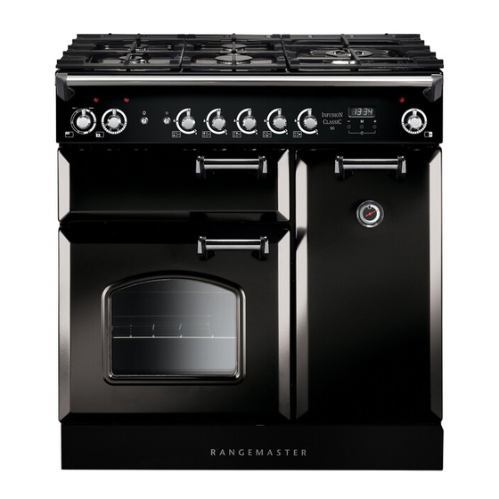
Cooker Overview DocNo.020-0006 - Overview - 90DF - Prof+ Fig. 2.1 The 90 dual fuel cooker (Fig. 2.1) has the following features: Fig. 2.2 5 hotplate burners including a wok burner A control panel incorporating a timer A glide-out grill Main fan oven Tall fan oven Hotplate Burners... -
Page 11: Wok Burner
If, when you let go of the control knob, the burner goes out, Fig. 2.3 then the FSD has not been bypassed. Turn the control knob to the OFF position and wait for one minute before you try again, this time making sure to hold in the control knob for slightly longer. -
Page 12: The Wok Cradle (Optional Extra)
The Wok Cradle (optional extra) Fig. 2.9 The wok cradle is designed to fit a 35 cm wok. If you use a different wok, make sure that it fits the cradle. Woks vary very widely in size and shape. It is important that the wok sits down on the pan support –... -
Page 13: The Glide-Out Grill
The Glide-out Grill Fig. 2.15 CAUTION: Accessible parts may be hot when the grill is in use. Young children should be kept away. Open the door and pull the grill pan carriage forward using the handle (Fig. 2.15). The grill has two elements that allow either the whole area of the pan to be heated or just the right-hand half. -
Page 14: The Ovens
The Ovens Fig. 2.18 The clock must be set to the time of day before the ovens will work. See the following section on ‘The Clock’ for instructions on setting the time of day. References to ‘left-hand’ and ‘right-hand’ ovens apply as viewed from the front of the appliance. -
Page 15: Accessories
Accessories Oven Shelves – Left-hand (Main) Oven Fig. 3.1 The cooker is supplied with 2 flat shelves (Fig. 3.1). Shelf guard The oven shelves can be easily removed and refitted. Pull the shelf forward until the back of the shelf is stopped by the shelf stop bumps in the oven sides (Fig. -
Page 16: Button Clock
3 Button clock Using the clock Fig. 4.1 You can use the clock to turn the programmable oven on and off. The clock must be set to the time of day before the oven will work. NOTE: When using the timer functions, first set the clock as ArtNo.306-0001 - 3-button clock required before setting the oven temperature. - Page 17 When the ‘stop time’ is reached an alarm will sound and Fig. 4.7 the oven will stop working. The word ‘AUTO’ will flash on the display (Fig. 4.6). Press any button to stop the alarm and return to manual cooking. If the alarm is not stopped, it will stop ArtNo.306-0001 - 3-button clock automatically after 7 minutes.
-
Page 18: Cooking Tips
Cooking tips Tips on cooking with the timer General oven tips If you want to cook more than one dish, choose dishes that The wire shelves should always be pushed firmly to the back require approximately the same cooking time. However, of the oven. -
Page 19: Cooking Table
Cooking Table The oven control settings and cooking times given in the table below are intended to be used as a Top (T) guide only. Individual tastes may require the temperature to be altered to provide a preferred result. ArtNo.050-0007 Centre (C) Oven shelf positions Food is cooked at lower temperature in a fan oven than in a conventional oven. -
Page 20: Cleaning Your Cooker
Cleaning your cooker Essential Information Fig. 7.1 Isolate the electricity supply before carrying out any thorough cleaning. Allow the cooker to cool. NEVER use paint solvents, washing soda, caustic cleaners, biological powders, bleach, chlorine based bleach cleaners, coarse abrasives or salt. DO NOT mix different cleaning products –... -
Page 21: The Griddle
The Griddle Fig. 7.5 ArtNo.331-0003 Grill frame out, no pan Always clean the griddle after use. Allow it to cool completely before removing. Immerse the griddle plate in hot soapy water. Use a soft cloth or, for stubborn stains, a nylon washing up brush. -
Page 22: Ovens
Glass Fronted Door Panels Fig. 7.8 The oven door front panels can be taken off so that the glass panels can be cleaned. Move the cooker forward to gain access to the sides (see the ‘Moving the Cooker’ section under ‘Installation’). -
Page 23: Cleaning Table
Cleaning table Cleaners listed are available from supermarkets or electrical retailers as stated. For enamelled surfaces use a cleaner that is approved for use on vitreous enamel. Regular cleaning is recommended. For easier cleaning, wipe up any spillages immediately. Hotplate Part Finish Recommended Cleaning Method... -
Page 24: Troubleshooting
Troubleshooting Hotplate/Cooktop ignition or hotplate burners faulty Food is cooking too slowly, too quickly, or burning Is the power on? Is the clock illuminated? Cooking times may differ from your previous oven. If not, there maybe something wrong with the power supply. Check that you are using the recommended temperatures and shelf positions –... - Page 25 Oven light is not working Fig. 8.1 The bulb has probably burnt out. You can buy a replacement bulb (which is not covered under the warranty) from a good electrical shop. Ask for a 40W - 230V halogen lamp (G9) (Fig.
-
Page 26: Installation
INSTALLATION Check the appliance is electrically safe and gas sound when you have finished. Installation Dear Installer In the UK the cooker must be installed in accordance with: Before you start your installation, please complete the details below, so that, if your customer has a problem relating to •... -
Page 27: Location Of Cooker
INSTALLATION Check the appliance is electrically safe and gas sound when you have finished. Location of Cooker Checking the Parts: The cooker may be installed in a kitchen/kitchen diner but 3 pan supports Splashback NOT in a room containing a bath or shower. This appliance is designed for domestic cooking only. -
Page 28: Positioning The Cooker
INSTALLATION Check the appliance is electrically safe and gas sound when you have finished. Positioning the Cooker ArtNo.105-0008 - 100DF 2BC cooker min spacings Fig. 9.1 Fig. 9.1 and Fig. 9.2 show the minimum recommended 75 mm 75 mm distance from the cooker to nearby surfaces. 650 mm The cooker should not be placed on a base. -
Page 29: Completing The Move
INSTALLATION Check the appliance is electrically safe and gas sound when you have finished. Make 10 complete (360°) turns clockwise. Fig. 9.5 Make sure you lower BOTH REAR ROLLERS. Completing the Move Unfold the rear edge of the cardboard base tray. Open the grill door and right-hand oven door so that you can get a good grip on the bottom of the fascia panel as you move the oven (Fig. -
Page 30: Gas Connection
INSTALLATION Check the appliance is electrically safe and gas sound when you have finished. You are recommended to use a spirit level on a shelf in one of Fig. 9.11 the ovens to check for level. Pipework Pipework Place the cooker in its intended position taking care not to twist it within the gap between the kitchen units as damage may occur to the cooker or the units. -
Page 31: Pressure Testing
INSTALLATION Check the appliance is electrically safe and gas sound when you have finished. Pressure Testing Current Operated Earth Leakage Breakers The gas pressure can be measured at one of the hotplate The combined use of your induction cooker and other burner injectors (not the wok burner). -
Page 32: Final Fitting
INSTALLATION Check the appliance is electrically safe and gas sound when you have finished. Final Fitting Fig. 9.15 Fitting the Handles and Handrail Remove the 4 mm Allen screws from the doors (Fig. 9.15). Fit the door handles and secure using the 4 mm screws. The handles should be above the fixings. -
Page 33: 10. Conversion To Lp Gas
WARNING – SERVICING TO BE CARRIED OUT ONLY BY AN AUTHORISED PERSON Disconnect from electricity and gas before servicing. Check appliance is safe when you have finished. 10. Conversion to LP Gas Check the ‘Technical Data’ section at the back of the book Fig. -
Page 34: Pressure Testing
WARNING – SERVICING TO BE CARRIED OUT ONLY BY AN AUTHORISED PERSON Disconnect from electricity and gas before servicing. Check appliance is safe when you have finished. Pressure Testing Connect the appliance to the gas supply. The gas pressure can be measured at one of the hotplate burner jets (not a wok burner). -
Page 35: 11. Circuit Diagram
11. Circuit Diagram P095199 P095199 P095199 The connections shown in the circuit diagram are for single-phase. The ratings are for 230 V 50 Hz. Code Description Code Description Code Colour Grill front switch Oven Fan Blue Grill energy regulator Clock / Timer Brown Left-hand grill element Cooling fan... -
Page 36: 12. Technical Data
29 mbar 230/400 V 50 Hz Propane 37 mbar See the appliance badge for test pressures. Dimensions Model Classic 90 Dual Fuel Overall height Minimum 905 mm Maximum 930 mm Overall width 900 mm Overall depth 608 mm excluding handles, 670 mm including handles... - Page 37 Hotplate Efficiency Brand Rangemaster Model Identification Classic Size Type Dual Fuel Type of Hob Number of gas burners Auxiliary / Small Burner (EE gas burner) Semi Rapide / Medium Burner (EE gas burner) Semi Rapide / Medium Burner (EE gas burner)
- Page 38 Oven Data Brand Rangemaster Model identification Classic Mass Type of oven Electric Number of cavities Left-hand Efficiency Fuel type Electric Cavity type Fanned Power - conventional Power - forced air convection Volume Litres Energy consumption (electricity) - conventional kWh / cycle...
- Page 39 • Has not been repaired by persons or organisations other than those authorised to act on behalf of AGA Rangemaster. Date of Purchase Exceptions: • Items not included under the free 1 year guarantee Installer’s Name &...
- Page 40 Registered Office: c/o Aga Rangemaster, Meadow Lane, Long Eaton, Nottingham, NG10 2GD Rangemaster continuously seeks improvements in specification, design and production of products and thus, alterations take place periodically. Whilst every effort is made to produce up-to-date literature, this brochure should not be regarded as...
Need help?
Do you have a question about the Classic 90 Dual Fuel and is the answer not in the manual?
Questions and answers