Table of Contents
Advertisement
Quick Links
Advertisement
Table of Contents
Troubleshooting

Subscribe to Our Youtube Channel
Related Manuals for innovair Dettson SLIM 24 HH EVO


Summary of Contents for innovair Dettson SLIM 24 HH EVO
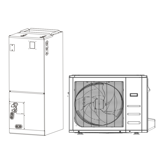
- Page 1 SLIM 24 HH Installation and Owner's Manual High Efficiency Heat Pump System Up to 19 SEER R410a Appearance of unit may vary. IMPORTANT NOTE: Read this manual carefully before installing or operating your new unit. Make sure to save this manual for future reference.
-
Page 2: Table Of Contents
Table of Contents Safety Precautions ......................... 4 Indoor Unit Parts And Major Functions ................... 8 Unit Parts ............................8 Operating Conditions ........................8 Features ............................9 Energy Saving Tips ..........................9 Care and Maintenance ......................10 Cleaning Your Indoor Unit ......................10 How To Clean The Air Filter ...................... - Page 3 Table of Contents Wiring ..........................40 Outdoor Unit Wiring ........................41 Indoor Unit Wiring ......................... 42 Control Logic ..........................46 LED Display ............................. 46 DIP Switch Definitions ........................47 Air Evacuation........................52 Preparations and Precautions ......................52 Evacuation Instructions ........................52 Note on Adding Refrigerant ......................
-
Page 4: Safety Precautions
Safety Precautions Read Safety Precautions Before Operation and Installation Incorrect installation due to ignoring instructions can cause serious damage or injury. The seriousness of potential damage or injuries is classified as either a WARNING or CAUTION. NOTE CAUTION WARNING This symbol refers to practices that are not This symbol indicates the This symbol indicates the... - Page 5 CAUTION Turn off the unit and disconnect the power if you are not going to use it for a long time. • Turn off and unplug the unit during storms. • Make sure that water condensation can drain unhindered from the unit. •...
- Page 6 WARNINGS FOR PRODUCT INSTALLATION 1. Installation must be performed by an authorized dealer or specialist. Defective installation can cause water leakage, electrical shock, or re. 2. Installation must be performed according to the installation instructions. Improper installation can cause water leakage, electrical shock, or re. (In North America,installation must be performed in accordance with the requirement of NEC and CEC by authorized personnel only.) 3.
- Page 7 Note about Fluorinated Gasses(Not applicable to the unit using R290 Refrigerant) This unit unit contains fluorinated greenhouse gasses. For specific information on the type of gas and the amount, please refer to the relevant label on the unit itself or “Owner's Manual - Product Fiche ”...
-
Page 8: Indoor Unit Parts And Major Functions
Indoor Unit Parts And Major Functions Unit Parts Operating Conditions Use the system under the following temperatures for safe and effective operation. If the unit is used under different conditions, it may malfunction or become less efficient. Air outlet COOL mode HEAT mode DRY mode 17°C - 32°C... -
Page 9: Features
To further optimize the performance of your unit, do the following: Keep doors and windows closed. • Limit energy usage by using TIMER ON and TIMER OFF functions. • Do not block air inlets or outlets. • Regularly inspect and clean air lters. •... -
Page 10: Care And Maintenance
Care and Maintenance Cleaning Your Indoor Unit BEFORE CLEANING OR MAINTENANCE ALWAYS TURN OFF YOUR UNIT SYSTEM AND DISCONNECT ITS POWER SUPPLY BEFORE CLEANING OR MAINTENANCE. • Contact an authorized service technician for repair or maintenance. Improper repair and maintenance may cause water leakage, electrical shock, or fire, and may void your warranty. -
Page 11: How To Clean The Air Filter
Care and Maintenance WARNING: DO NOT REMOVE OR CLEAN THE FILTER BY YOURSELF Removing and cleaning the filter can be dangerous. Removal and maintenance must be performed by a certified technician. How To Clean The Air Filter The filter prevents dust and other particles from entering the indoor unit. Dust buildup can reduce the efficiency of the unit. -
Page 12: Maintenance - Long Periods Of Non-Use
CAUTION Before changing the filter or cleaning, turn off the unit and disconnect its power supply. • When removing filter, do not touch metal parts in the unit. The sharp metal edges can cut you. • Do not use water to clean the inside of the indoor unit. This can destroy insulation and cause •... -
Page 13: Troubleshooting
Troubleshooting SAFETY PRECAUTIONS If any of the following conditions occurs, turn o your unit immediately! The power cord is damaged or abnormally warm • You smell a burning odor • The unit emits loud or abnormal sounds • A power fuse blows or the circuit breaker frequently trips •... -
Page 14: Troubleshooting
Issue Possible Causes The outdoor unit The unit will make di erent sounds based on its current operating mode. makes noises Dust is emitted from The unit may accumulate dust during extended periods of non-use, which will be either the indoor or emitted when the unit is turned on. - Page 15 Problem Possible Causes Solution Wait for the power to be restored Power failure The power is turned o Turn on the power The unit is not The fuse is burned out Replace the fuse working The Unit’s 3-minute protection Wait three minutes after restarting the unit has been activated Turn timer o Timer is activated...
- Page 16 The design and specifications are subject to change without prior notice for product improvement. Consult with the sales agency or manufacturer for details. Any updates to the manual will be uploaded to the service website, please check for the latest version.
-
Page 17: Accessories
Accessories The unit system comes with the following accessories. Use all of the installation parts and accessories to install the unit. Improper installation may result in water leakage, electrical shock and fire, or equipment failure. Accessories (Packed with the indoor unit) Name Shape Quantity... -
Page 18: Indoor Unit Installation
Indoor Unit Installation Indoor Unit Parts IMPORTANT Please apply sealant around the places where the wires, refrigerant pipes and condensate coil compartment (Access panel Removed) pipes enter the cabinet. Up ow drain pan Indoor Unit Installation Instructions The indoor unit should be installed in a location that meets the following requirements: Horizontal drain pan Enough room for installation and maintenance. -
Page 19: Recommended Distances Between The Indoor Unit
WARNING There must be an airtight seal between the bottom of the unit and the return air plenum. Use fiberglass sealing strips, caulking, or equivalent sealing method between the plenum and the unit to ensure a tight seal. Return air must not be drawn from a room where this unit or any gas-fueled appliance (i.e., water heater), or carbon monoxide-producing device (i.e., wood fireplace) is installed. -
Page 20: Installation Place
Note Recommended size of filter The filter in this product is for energy efficiency sampling tests only. The use of this filter meets the requirements of the UL900 standard. (unit: mm/inch) MODEL(Btu/h) inch inch inch 12-24K 406.4 25.4 30-48K 495.3 19-1/2 25.4 584.2... -
Page 21: Mount Positions
IMPORTANT A field-fabricated secondary drain pan, with a drain pipe to the outside of the building, is required in all installations over a finished living space or in any area that may be damaged by overflow from the main drain pan. In some localities, local codes may require a secondary drain pan for any horizontal installation. -
Page 22: Reversing Installation Instructions
NOTE Reversing Installation Instructions The unit can be installed in any of the For the Horizontal right installation and Vertical following orientations: upward flow, down installation, the direction of the evaporator downward flow, left horizontal or right should be changed . Please do it according to the horizontal. - Page 23 6. Take out the evaporator and drain pan and 4. Remove T1、T2、T2A、T2B temperature sensor rotate 180°. plug、electronic expansion valve (EEV) T2A&T2B 7. Adjust the position of the mounting parts. NOTE T2A and T2B are only available for some models. 5. . Remove T1、T2、T2A、T2B temperature sensor and electronic expansion valve (EEV) wire ties.
- Page 24 10. The evaporator is assembled in place. 9. Reinstall T1、T2、T2A、T2B temperature sensor plug electronic expansion valve and tie up the temperature sensor wires. NOTE The wire body needs to pass through the wire groove from the water receiving tray and be stuck on the hook of the water receiving tray.
- Page 25 13. Reassemble the upper cover. 14. Reinstal the lter and lter cover plate. 15. Connect the pipes. 16. Install the drainage pipes. Page 2 5 ...
-
Page 26: Installation Of Electric Auxiliary Heat Module
NOTE Installation of Electric Auxiliary Heat Module (for some models)(not supplied) Use only modules that are compatible and certified for use with the model. Please refer to the electric auxiliary heater model Accessories specifications for additional details to ensure Name Shape Quantity proper selection and installation. - Page 27 2. Remove the terminal block and power cord, 4. Tighten the xing screws. loosen the screws, and remove the electric screws auxiliary heating cover. 5. Wiring according to the wiring nameplate. 3. Install the electric auxiliary heating component 6. Install the upper cover. into the chassis shell along the front direction, 7.
- Page 28 After the electric heating wiring is connected, NOTE please check before power on: Electric auxiliary heating wiring diagram Check all wiring and ensure reliable connection packed with the accessories. of wire body. Check the electric heating fixing screw, and Please paste the wiring diagram in the inside if the screw is fixed reliably.
-
Page 29: Auxiliary Heater Electrical Data
Page 2 9 ... -
Page 30: Electric Auxiliary Heating Wiring Diagram
Electric Auxiliary Heating Wiring Diagram 3KW/5KW HEAT KIT 8KW/10KW HEAT KIT :thermal cut-out :thermal cut-out :thermal link, self-resetting :thermal link, self-resetting Aux-Heat HTR1 control signal TL 1 R E D T C O1 BLACK 0 0 0 0 0 0 0 0 0 0 0 0 0 0 0 0 TO INDOOR UNIT RELAY1 HTR1... -
Page 31: Outdoor Unit Installation
Outdoor Unit Installation install unit in the following locations: DO NOT Space requirement Near an obstacle that will block air inlets and Install the unit by following local codes and outlets regulations , there may be differ slightly between Near a public street, crowded areas, or where different regions. -
Page 32: Unit Mounting Dimensions
Step 3: Anchor outdoor unit Step 2: Install drain joint (Heat pump unit only) The outdoor unit can be anchored to the ground or to a wall-mounted bracket with Before bolting the outdoor unit in place, you must install the drain joint at the bottom of the unit. bolt(M10). - Page 33 (unit: mm/inch) If you will install the unit on the ground or on a concrete mounting platform, Outdoor Unit Dimensions Mounting Dimensions do the following: inch inch inch inch inch 1. Mark the positions for four expansion bolts 31-11/16 554 21-13/16 330 13 20-1/8 12-1/2...
-
Page 34: Drainpipe Installation
Drainpipe Installation Indoor Drainpipe Installation The drainpipe is used to drain water away from the unit. Improper installation may cause unit 1. Cover the drainpipe with heat insulation to and property damage. prevent condensation and leakage. CAUTION These units operate with a positive pressure at the drain connections and a drain trap is required. - Page 35 3. Pass the drain hose through the wall hole. Anti-syphon >50mm(2”) air vent Make sure the water drains to a safe location >50mm(2”) where it will not cause water damage or a >50mm(2”) slipping hazard. Vent T Lean over 1/50 Drain Trap NOTE The drainpipe outlet should be at least 5cm...
-
Page 36: Refrigerant Piping Connection
Refrigerant Piping Connection Safety Precautions CAUTION Oil traps WARNING If oil flows back into the outdoor unit’s compressor, • All field piping must be completed by a this might cause liquid compression or deterioration licensed technician and must comply with of oil return. -
Page 37: Connection Instructions - Refrigerant Piping
Name Shape Quantity(PC) 6.35( 1/4 i n) Φ Liquid side 9.52( 3/8in) Φ Parts you must purc hase Connecting pipe separately. Consult the dealer 12.7( 1/2in) Φ assembly about the proper pipe size of 16( 5/8in) Φ the unit you purchased. Gas side 19( 3/4in) Φ... - Page 38 5. Clamp are form on the end of the pipe. NOTE: Use both a spanner and a torque wrench The end of the pipe must extend beyond the are when connecting or disconnecting pipes to/from form. the unit. Flare form Pipe Place aring tool onto the form.
- Page 39 After the unit is installed, Wrap the valve body with 7. Thread this pipeline through the wall and insulation material and make sure the valve is sealed. connect it to the outdoor unit. 8. Insulate all the piping, including the valves of the outdoor unit.
-
Page 40: Wiring
Wiring BEFORE PERFORMING ANY Make sure that you do not cross your electrical wiring with your signal wiring. ELECTRICAL WORK, READ THESE This may cause distortion and interference. REGULATIONS The unit must be connected to the 1. All wiring must comply with local and national main outlet. -
Page 41: Outdoor Unit Wiring
Air switch (purchased seperately) Air switch (purchased seperately) Indoor unit power wires E lec tric al h eater u nit power w ires Outdoor unit power wires E lec tric al Indoor unit heater Outdoor unit unit Indoor & Outdoor connective wires (purchased seperately) NOTE... -
Page 42: Indoor Unit Wiring
WARNING 4. Clamp down the cable with the cable clamp. 5. Insulate unused wires with electrical tape. ISOLATE THE POWER SUPPLY LEADS AND Keep them away from any electrical or metal COMMUNICATION LEADS BY THE STRAIN parts. RELIF AND KEEP POWER SUPPLY LEADS 6. - Page 43 CAUTION WARNING While connecting the wires, please strictly • Please refer to the wiring nameplate for the follow the wiring diagram. wiring method. Do not connect the power The refrigerant circuit can become very • cord to the communication line, as this may hot.
- Page 44 Connection method C: • Wiring for 3H and 2C thermostat The following wiring diagram are suitable for the W1/E AHU and ODU with 24V thermostat. Non-communication scheme wiring reference • Wiring for 4H and 2C thermostat W1/E THERMOSTAT Y1 Y2 B W D W1 W2 INDOOR UNIT...
- Page 45 • Wiring for 1H and 1C thermostat • Liquid level switch interface The unit has a liquid level detection interface. If you choose this function, you need to purchase a liquid level switch by yourself, connect to the CN5 interface, and remove J1. When the water THERMOSTAT receiving pan is full, the water level switch is W1 W2...
-
Page 46: Control Logic
• Dehumidi cation control wiring Control Logic Indoor unit Connector Connector Purpose HUMIDISTAT First period cooling S4-1 DIP switch of Y/Y2 Second period cooling Perform disconnection and short-circuit to Heating(Four-way valve) achieve partition, control or dehumidifcation Heating operation Electric heating operation 1 Dehumidi cation control requires indirect Electric heating operation 2 humidi er at DH and R. -
Page 47: Dip Switch Definitions
DIP Switch Definitions Function DIP switch Address 24V thermostat interface DIP switch 24V control DIP switch Function DIP switch Static pressure DIP switch Page 4 7 ... - Page 48 ON for 30 minutes, OFF DIP switch functions: SW2-2 for 15 minutes • OFF no delayed start SW2-3 This code mainly controls and selects the type of ON delayed start activated unit. It is recommended that this is adjusted under the supervision of technical personnel. SW2-4: This dial code controls the allowable opening temperature of electric heating or SW1-1: Selects the Communication Mode, (ON: 24V...
- Page 49 Address DIP switch: Static pressure DIP switch: Address dialing S1+S2: When a centralized controller is used, address dialing is required. The code is only valid for 1-3. The composition of the binary code corresponds to a different Network address: The address silkscreen is a NET static pressure of the wind profile.
- Page 50 Air volume table 000 gear (default) Model 001 air volume(CFM) 010 air volume(CFM) 011 air volume(CFM) air volume(CFM) 10KW 10KW 、8KW 5KW、3KW 15KW 15KW 、8KW 10KW、8KW 5KW、3KW 1100 1040 15KW 15KW 、10KW 10KW、8KW 8KW、5KW 1320 1255 1190 1125 20KW 15KW 10KW、8KW 8KW、5KW 1760...
- Page 51 Page 5 1 ...
-
Page 52: Air Evacuation
Air Evacuation Preparations and Precautions Close the Low Pressure side of the manifold gauge, and turn off the vacuum pump. Air and foreign matter in the refrigerant circuit can Wait for 5 minutes, then check that there has cause abnormal rises in pressure, which can damage been no change in system pressure. -
Page 53: Note On Adding Refrigerant
Note on Adding Refrigerant Some systems require additional charging depending on pipe lengths. The standard pipe length varies according to local regulations. For example, in North America, the standard pipe length is 7.5m (25’). In other areas, the standard pipe length is 5m (16‘). The refrigerant should be charged from the service port on the outdoor unit’... -
Page 54: Test Run
Test Run 5. For the Outdoor Unit Before Test Run a. Check to see if the refrigeration system is A test run must be performed after the entire leaking. system has been completely installed. Confirm b. Make sure there is no vibration or abnormal the following points before performing the test: noise during operation.
Need help?
Do you have a question about the Dettson SLIM 24 HH EVO and is the answer not in the manual?
Questions and answers