Advertisement
Quick Links
SERVICE MANUAL
GR-DX75U
For disassembling and assembling of MECHANISM ASSEMBLY, refer to the SERVICE MANUAL No.86700(MECHANISM ASSEMBLY).
SPECIFICATIONS
Camcorder
General
Power supply
: DC 11.0 V
(Using AC Adapter)
DC 7.2 V
(Using battery pack)
Power consumption
LCD monitor off,
viewfinder on : Approx. 3.4 W
LCD monitor on,
viewfinder off : Approx. 4.6 W
Dimensions
(W x H x D)
: 55 mm x 102 mm x 96 mm (2-1/4"
x 4-1/16" x 3-13/16")
(with the LCD monitor closed and
the viewfinder pushed back in)
Weight
: Approx. 440 g (0.97lbs) (without
grip belt) (GR-DX300)
Approx. 450 g (1lbs) (without grip
belt) (GR-DX95/DX75)
Operating
temperature
: 0°C to 40°C (32°F to 104°F)
Operating
humidity
: 35% to 80%
Storage
temperature
: –20°C to 50°C (–4°F to 122°F)
Pickup
: 1/4" CCD (GR-DX300)
1/6" CCD (GR-DX95/DX75)
Lens
: F 1.8, f = 3.8 mm to 38 mm (0.15"
to 1.5"),
10:1 power zoom lens
(GR-DX300)
F1.6, f =2.7 mm to 43.2 mm (0.11"
to 1.7"),
16:1 power zoom lens
(GR-DX95/DX75)
Filter diameter
: ø30.5 mm (1.2")
LCD monitor
: 3" diagonally measured, LCD
panel/TFT active matrix system
(GR-DX300/DX95)
2.5" diagonally measured, LCD
panel/TFT active matrix system
(GR-DX75)
Viewfinder
: Electronic viewfinder with 0.24"
black/white LCD
Speaker
: Monaural
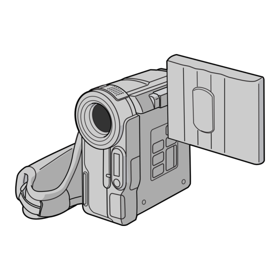
DIGITAL VIDEO CAMERA
S
(The specifications shown pertain specifically to the model GR-DX75US, GR-DX95US and GR-DX300US.)
Digital Video Camera
Format
: DV format (SD mode)
Signal format
: NTSC standard
Recording/
Playback format : Video: Digital component recording
: Audio: PCM digital recording,
32 kHz 4-channel (12-bit),
48 kHz 2-channel (16-bit)
Cassette
: Mini DV cassette
Tape speed
: SP : 18.8 mm/s
LP : 12.5 mm/s
Maximum
recording time
: SP : 80 min.
(using 80 min.
LP : 120 min.
cassette)
Digital Still Camera Function
Storage media
: SD Memory Card/MultiMediaCard
Compression
system
: Still image
Moving image : MPEG4
File size
: 4 modes (1600 x 1200 pixels*,
1280 x 960 pixels*,
1024 x 768 pixels,
640 x 480 pixels)
Picture quality
: 2 modes (FINE/STANDARD)
Approximate
number of
storable images :
pg. 18.
* GR-DX300 only.
Specifications shown are for SP mode unless otherwise indicated. E & O.E. Design and specifications subject
to change without notice.
COPYRIGHT © 2003 VICTOR COMPANY OF JAPAN, LTD
, GR-DX95U
Connectors
S/AV
S-Video output : Y : 1 V (p-p), 75 Ω, analog
S-Video input
Video output
Video input
Audio output
Audio input
Edit
DV
Output
Input
: JPEG
(compatible)
USB
(compatible)
Power requirement
U.S.A and Canada : AC 120 V`, 60 Hz
Other countries
Output
S
C : 0.29 V (p-p), 75 Ω, analog
: Y : 0.8 V (p-p) – 1.2 V (p-p), 75 Ω,
analog
C : 0.2 V (p-p) – 0.4 V (p-p), 75 Ω,
analog
: 1 V (p-p), 75 Ω, analog
: 0.8 V (p-p) – 1.2 V (p-p), 75 Ω,
analog
: 300 mV (rms), 1 kΩ, analog,
stereo
: 300 mV (rms), 50 kΩ, analog,
stereo
: ø3.5 mm (0.14"), 2-pole
: 4-pin, IEEE 1394 compliant
: 4-pin, IEEE 1394 compliant
: 5-pin
AC Adapter
: AC 110 V to 240 V`, 50 Hz/60 Hz
: DC 11 V
, 1 A
GR-DX75US M3D327
GR-DX95US M3D337
No.86757
2003/06
Advertisement

Related Manuals for JVC GR-DX75US


Summary of Contents for JVC GR-DX75US
- Page 1 DIGITAL VIDEO CAMERA GR-DX75U , GR-DX95U For disassembling and assembling of MECHANISM ASSEMBLY, refer to the SERVICE MANUAL No.86700(MECHANISM ASSEMBLY). SPECIFICATIONS (The specifications shown pertain specifically to the model GR-DX75US, GR-DX95US and GR-DX300US.) Digital Video Camera Connectors Camcorder Format : DV format (SD mode)
-
Page 2: Table Of Contents
DISASSEMBLY ................................1-1 ADJUSTMENT ................................3-1 CHARTS AND DIAGRAMS ............................4-1 PARTS LIST ..................................5-1 DIFFERENT LIST DIFFERENT TABLE OF FEATURE The following table indicate main different points between models GR-DX75US and GR-DX95US. MODEL GR-DX75US GR-DX95US ITEM LCD MONITOR 2.5 INCH 3.0 INCH... -
Page 3: Important Safety Precautions
Important Safety Precautions Prior to shipment from the factory, JVC products are strictly inspected to conform with the recognized product safety and electrical codes of the countries in which they are to be sold. However, in order to maintain such compliance, it is equally important to implement the following precautions when a set is being serviced. - Page 4 Safety Check after Servicing Examine the area surrounding the repaired location for damage or deterioration. Observe that screws, parts and wires have been returned to original positions, Afterwards, perform the following tests and confirm the specified values in order to verify compli- ance with safety standards.
-
Page 5: Disassembly
SECTION 1 DISASSEMBLY 1.1 Before disassembling • Torque driver Be sure to use to fastening the mechanism and exterior parts 1.1.1 Precaution because those parts must strictly be controlled for tighten- • Be sure to disconnect the power supply unit prior to mount- ing torque. - Page 6 1.2.2 Disassembly procedure [FINAL ASS'Y] [LOWER ASS’Y(F), LOWER ASS’Y(G)] Step Step Part Name Fig. No. Point Note Point Note Part Name Fig. No. FRONT ASS’Y(G) 1-2-2a (S132), 2(S131), OP F. ASS’Y (S560), (S133), (S130), SD CN302(WR551a), TOP COVER, MIC COVER, (S558), BKT(OP) - - - - - - - - - - - - - - - - - - - - - - - - - - (S125), (S126), 2(S129),...
- Page 7 Table.1 WIRE(FPC) CONNECTION TABLE <M2> FINAL ASS'Y MIC COVER PWB NAME CN No. ASS'Y NAME WIRE(FPC)NAME MAIN PWB ASS'Y CN101 LOWER ASS'Y(F) BATT.TERM. MAIN PWB ASS'Y CN102 LOWER ASS'Y(F) MAIN PWB ASS'Y CN103 MECHA(A) ASS'Y LOAD.MOTOR TOP COVER MAIN PWB ASS'Y CN104 MECHA(A) ASS'Y DRUM MOTOR...
- Page 8 <M2> LOWER ASS'Y(F) PROCESSING E-CARD WIRE (ONLY THE MODEL OF OP ASS' Y OF K185). DRAWING FOR SPACER STICKING. [For Non Megapixel CCD MODEL] [J7C: Megapixel CCD MODEL] [K185: Non Megapixel CCD MODEL] BKT(OPJ7C) SPACER IS NOT MIC ASS'Y PROTRUDED FROM ARM BRACKET.
- Page 9 <M2> UPPER ASS'Y(G) COVER(TOP/UPP)L COVER(TOP/UPP)R MONI.LOCK ASS'Y SUB OPE UNIT MONITOR ASS'Y(G) (Refer to the Exploded view for this part.) UPWARDS U.CASE ASS'Y (WR601a) PASTE FRAME(UPPER) ASS'Y SOLDERING 2 POINT SCREW * SPEAKER BRACKET(SPEAKER) * Mark*: This part was deleted on the way of production. UPPER ASS'Y(G) LYH20626 CONCLUSION SCREW TORQUE TABLE PART.NO...
- Page 10 <M2> MONITOR ASS'Y(G) CONCLUSION SCREW TORQUE TABLE PROCESSING MONITOR FPC. PUTTING OF SPACER(A). (WR802b) THIS HOLE IS NOT PART NO. SETTING TORQUE HINGE UNIT ASS'Y PLUGGED UP. MONITOR P. ASS'Y (2.5 INCH) 0.2 ±0.02 N•m VALLEY FOLDING 0.055 ±0.01 N•m DETECT SWITCH MOUNTAIN FOLDING THE END OF PWB IS...
- Page 11 <M2> VF ASS'Y(G) CONCLUSION SCREW TORQUE TABLE BLOW OUT AIR. VFBW BOARD ASS'Y PART.NO TORQUE VFCL BOARD ASS'Y 0.09 ±0.009 N•m ALL SCREW B.LIGHT CASE B.LIGHT CASE BLOW OUT AIR. SHEET(DIFF) SHEET(POLA) CUSHION(LCD) CUSHION(LCD)3 BLOW OUT AIR. LCD MODULE BLOW OUT AIR. PASTE TAPE TO LCD RESPECT, AND PEEL OFF TAPE.
- Page 12 1.4 EMERGENCY DISPLAY Whenever some abnormal signal is input to the syscon CPU, an error number (E01, as an example) is displayed on the LCD monitor or (in the Electronic view finder). In every error status, such the message as shown below alter- REMOVE AND UNIT IN nately appear over and over.
-
Page 13: Adjustment
Guide driver (Hexagonal) PTS40844-2 KSMM-01 D-770-1.27 tem. Please contact to JVC Service for detail information. • OP BLOCK ASSEMBLY • EEPROM (IC1003 of MAIN board) [Megapixel CCD MODEL] • EEPROM (IC1005 of MAIN board) [Non Megapixel CCD MODEL] INF adjustment lens... - Page 14 • Torque driver • Service support system Be sure to use to fastening the mechanism and exterior parts To be used for adjustment with a personal computer. Soft- because those parts must strictly be controlled for tightening ware can be downloaded also from JS-net. torque.
- Page 15 3.1.4 Jig connector cable connection 3.1.4.1 Preparation The Jig connector cable (YTU93106B) has been provided for GR-DV2000 series. And it has been connected only 9 termi- nals for low cost, although it has 30 terminals. Now it can be used another series camcorder, but all the terminals have to be connected by soldering wires.
- Page 16 JVC SERVICE & ENGINEERING COMPANY OF AMERICA DIVISION OF JVC AMERICAS CORP. www.jvcservice.com(US Only) JVC CANADA INC. Head office : 21 Finchdene Square Scarborough, Ontario M1X 1A7 (416)293-1311 Printed in Japan 0306 VP...
- Page 40 SERVICE MANUAL MECHANISM ASSEMBLY 86700 2003 DVC MECHANISM VHS-C MECHANISM VHS MECHANISM <DVC MECHANISM> <VHS-C MECHANISM> <VHS MECHANISM> TABLE OF CONTENTS JIGS AND TOOLS ..............1-1 SPECIFIC SERVICE INSTRUCTIONS .
- Page 41 SECTION 1 JIGS AND TOOLS TOOLS REQUIRED FOR ADJUSTMENTS 1. Torque driver Torque driver Be sure to use to fastening the mechanism and exterior parts YTU94088 YTU94088-003 because those parts must strictly be controlled for tightening torque. Torque setting value of torque driver is limited. At the values over the maximum torque setting value, fasten a screw manually not to damage the screw thread.
- Page 42 SECTION 2 SPECIFIC SERVICE INSTRUCTIONS 2.1 DVC MECHANISM 2.1.1 Precautions (1) When fastening parts, pay careful attention to the tighten- ing torque of each screw. Unless otherwise specified, tight- en a screw with the torque of 0.055 N•m (0.56 kgf•cm). (2) Be sure to disconnect the set from the power supply before fastening and soldering parts.
- Page 43 2.1.3 DISASSEMBLY AND ASSEMBLY OF MECHANISM ASSEMBLY 2.1.3.1 General statement 2.1.3.2 Explanation of mechanism mode The mechanism should generally be disassembled/assembled in The mechanism mode of this model is classified into five modes the C.IN mode (ASSEMBLY mode). (Refer to Fig. 2-1-1,2-1-2.) as shown in Fig.
- Page 44 2.1.3.3 Mechanism timing chart MODE SHORT TU. P. B SLIDE TU. P. B SLIDE RELEASE EJECT C IN START START STOP PLAY PARTS MAIN CAM -12.40 (22.44 58.71 (69.53 (80.5 (150.58 ) (153.5 177.79 212.77 243.94 SUB CAM -16.97 (30.71 80.34 (95.14 (110.06...
- Page 45 2.1.4 DISASSEMBLY PROCEDURE TABLE MARK: # After assembly, perform adjustments. PART NAME FIG. POINT NOTE REMARKS [ 1 ] CASSETTE HOUSING ASSY Fig.2-1-14 3(S1),(L1a)-(L1e) NOTE 1 a,b,c,d ADJUSTMENT [ 2 ] UPPER BASE ASSY Fig.2-1-15 (S2),(L2a),(L2b) NOTE 2 [ 3 ] (S3a),2(S3b) ADJUSTMENT DRUM ASSY...
- Page 46 [ 1 ] (S1) (S2) (S1) (W4) [ 2 ] [ 4 ] (W5a) [ 5 ] (S6a) (W6) (W5b) (S6b) [ 3 ] (S6a) [ 6 ] (S11b) [ 9 ] (S35) [ 7 ] (S36) [10] (S35) [ 8 ] (S35) (S10) (P8)
- Page 47 < TOP VIEW > [24] [27] [ 2 ] [ 3 ] [21] [36] [35] [17] [20] [26] [23] [34] [18] [ 9 ] [ 8 ] [10] [ 7 ] [33] [22] [26] [12] [ 6 ] [ 4 ] [37] [25] [29]...
- Page 48 2.1.5 DISASSEMBLY/ASSEMBLY 2.1.5.1 [ 1 ] CASSETTE HOUSING ASSY NOTE 1a NOTE 1a: [ 1 ] Be careful not to damage any of the parts during work. NOTE 1b: (S1) Special care is required in mounting. NOTE1d NOTE 1c: When mounting, the CASSETTE HOUSING ASSY should be attached in the Eject status.
- Page 49 2.1.5.3 [ 4 ] REEL DISK ASSY(SUP) [ 5 ] REEL DISK ASSY(TU) (W4) [ 6 ] REEL COVER ASSY (W5a) NOTE 4: NOTE 4 Be careful not to attach the REEL DISK wrongly. The Supply [ 4 ] side can be identified by the white color at the center. NOTE 5a NOTE 5a: [ 5 ]...
- Page 50 2.1.5.4 [ 7 ] TENSION ARM ASSY [ 8 ] SLANT POLE ARM ASSY [ 9 ] TU ARM ASSY [10] SWING ARM ASSY NOTE 7: When detaching, remove the spring of the [12] PAD ARM ASSY in advance. Pay attention to the attachment position. [ 8 ] NOTE 8: NOTE 9...
- Page 51 2.1.5.5 [11] SLIDE DECK ASSY NOTE 11a: Each of the parts on the SLIDE DECK ASSY can be replaced separately. (S11b) When detaching the assembly, if there is no need to replace any of its parts, remove the SLIDE DECK ASSY as it is. (L11c) (L11b) NOTE 11b:...
- Page 52 2.1.5.7 [15] TENSION CTL LEVER ASSY [16] CENTER GEAR [17] PINCH ROLLER ARM FINAL ASSY [18] TENSION CTL PLATE ASSY [19] BRAKE CTL LEVER ASSY NOTES 15/16: NOTE 17 When mounting, pay attention to the correct positioning. (W17) [17] NOTE 17: Take care against grease attachment during work.
- Page 53 2.1.5.9 [26] BASE R ASSY [27] ROTARY ENCODER [28] GEAR COVER ASSY (S27) [29] MAIN CAM ASSY NOTE 27 NOTE 26: [27] When mounting, fold the sliding part to the inner side. (S27) NOTE 27: When mounting, pay attention to the correct positioning and the FPC layout.
- Page 54 2.1.5.11 [35] DRUM BASE ASSY [36] CAPSTAN MOTOR [37] MAIN DECK ASSY NOTES 35a/36: (S35) Since [36]CAPSTAN MOTOR is attached to [35]DRUM BASE (S36) ASSY, remove [36]CAPSTAN MOTOR together with (S35) [35]DRUM BASE ASSY when removing [36]CAPSTAN MO- TOR. (S35) [36]CAPSTAN MOTOR should not be separated from [35]DRUM BASE ASSY except when replacing them.
- Page 55 2.1.6 CHECKUP AND ADJUSTMENT OF MECHANISM PHASE [24] MODE GEAR [27] ROTARY ENCODER Align the MODE GEAR with the Main Deck Mount the ROT ARY ENCODER by aligning its mark ( Assembly hole. and the mark ( ) of the Main Deck Assembly. Note: Note: Be careful when handling the FPC during mounting.
- Page 56 2.1.7 MECHANISM ADJUSTMENTS 2.1.7.1 Adjustment of the slide guide plate Use Fig. 2-1-26 as the reference unless otherwise specified. (1) Set the PLAY mode. See Fig. 2-1-8. (2) Loosen the screws (A, B). (3) With the Main Deck and Slide Deck Assemblies pushed into the unit, tighten the screws (A, B) while applying pressure to the stud (shaft) on the Slide Guide plate.
- Page 57 2.1.7.2 Adjustment of the Tension Arm and Pad Arm As- semblies Use Fig. 2-1-27 as the reference unless otherwise specified. (1) Set the PLAY mode. See Fig. 2-1-8. (2) Loosen the screw A. (3) With the take-up side at the bottom, align the extreme end of the Tension Arm Assembly with the crossed grooves on the screw B that retains the Loading Motor Assembly and then tighten the screw A.
- Page 58 2.1.8 SERVICE NOTE Use the following chart to manage mechanism parts that are removed for disassembling the mechanism. [ 1 ] [ 2 ] CASSETTE HOUSING ASSY UPPER BASE ASSY [ 3 ] [ 4 ] REEL DISK ASSY(SUP) [ 6 ] REEL COVER ASSY DRUM ASSY [ 5 ]...
- Page 59 [15] PINCH ROLLER TENSION BRAKE CTL [16] [17] TENSION CTL CENTER GEAR [18] [19] ARM F ASSY CTL PLATE LEVER LEVER ASSY ASSY ASSY [20] MOTOR GUIDE [22] SLIDE LEVER 2 LOADING [21] [23] BRACKET RAIL ASSY ASSY PLATE ASSY ASSY [25] [24]...
- Page 60 2.1.9 SERVICE NOTE Use the following chart to manage screws. Fig.2-1-31 (No.86700)2-19...
- Page 61 2.1.10 REMARKS 2.1.10.1 Cleaning (1) For cleaning of the upper drum (particularly video heads), use fine-woven cotton cloth with alcohol soaks through. Do not move the cloth but turn the upper drum counterclock- wise. NOTE: Make sure not to move the cloth in the vertical direction to the video head, since it may cause damage of the video heads.
- Page 62 VHS-C MECHANISM 2.2.1 Precautions (1) When fastening parts, pay careful attention to the tighten- ing torque of each screw. Unless otherwise specified, tight- en a screw with the torque of 0.216 N•m (2.2 kgf•cm). Torque setting value of torque driver is limited. At the val- ues over the maximum torque setting value, fasten a screw manually not to damage the screw thread.
- Page 63 2.2.3 DISASSEMBLY/ASSEMBLY PROCEDRURE TABLE This procedure starts with the condition that the cabinet parts and deck parts. Also, all the following procedures for adjustment and parts replacement should be performed in STOP mode. When reassembling, perform the step(s) in the reverse order. REMOVAL INSTALLATION STEP/LOC.
- Page 64 [20] (S5a) (S5a) [31] (S6b) [25] (S7) (S7) (S7) (S5a) [21] (S5a) (S6b) (S5a) (S5a) (W1a) [22] (P1) (S5b) [27] (S5b) (S6d) (S6d) (W1a) (S6d) (S5c) [28] (W2) (S6d) [23] (S6d) (W2) (S6d) [34] (S6d) (W1b) (W1a) [29] [26] (S6d) (W8b) (S8) 39 (S8)
- Page 65 <TOP VIEW> [25] [26] [31] [37] [20] [21] [29] [19] [28] [22] [27] [23] [36] [17] [16] [14] [15] [18] [12] [34] [35] [30] [32] [33] [13] Fig.2-2-3 <BOTTOM VIEW > [24] [11] BRACKET (MECHA) [10] NOTE: In removing the ROTARY ENCODER, please remove the BRACKET(MECHA).
- Page 66 (W1a) [16] (S3a) (W3b) [12] [13] [17] (S3b) (P3) (P1) (W3a) (S1) (W3a) (W1a) [14] (W3a) [15] (W1a) (W1b) [11] [10] (S3a) (S3a) (S3a) (S3a) Fig.M3 Fig.M1 (W2) (S4a) [19] [20] (S4b) (W4) (S4b) (W2) [18] (S2) (W2) * 0.118 N . m (1.2 kgf . cm) Fig.M2 Fig.M4 (No.86700)2-25...
- Page 67 (S5a) [21] 14,15 (S5a) [31] 33,34,35 (S7) (S5a) [22] [29] [30] 17,18 (S5c) (S5b) [23] * 0.118 N . m (1.2 kgf . cm) Fig.M5 Fig.M7 21,22 36,37 38,39 (S6b) Catcher (S8) (S8) [25] [28] [37] [27] 25,26 (S6b) 27,28,29 (W8a) (S6b) (S6b)
- Page 68 2.2.4 CHECKUP AND ADJUSTMENT OF MECHANISM PHASE NOTE: Pay careful attention to the installing order and phase of mechanism parts of the loading system. [37] LOADING RING ASSEMBLY Align the two holes of the LOADING RING ASSEMBLY to those of MAIN DECK. [35] LOADING GEAR(T) ASSEMBLY Align the hole of the LOADING GEAR (T) ASSEMBLY to that of the MAIN...
- Page 69 2.2.5 SERVISE NOTE Use the following chart to manage screws. Fig.2-2-7 2-28 (No.86700)
- Page 70 2.2.6 REMARKS 2.2.6.1 Cleaning (1) For cleaning of the upper drum (particularly video heads), use fine-woven cotton cloth with alcohol soaks through. Do not move the cloth but turn the upper drum counterclock- wise. NOTE: Make sure not to move the cloth in the vertical direction to the video head, since it may cause damage of the video heads.
- Page 71 VHS MECHANISM 2.3.1 Notes 2.3.3 Setting the mechanism assembling mode This model’s mechanism relates closely to the rotary encoder The mechanism-assembling mode is provided with this mecha- and system control circuit (the rotary encoder is meshed with the nism. When disassembling and assembling, it is required to en- control cam).
- Page 72 2.3.4 Layout of the main mechanism parts Pole base assy T4 Main brake assy T3 A/C head (take-up Side) (take-up side) Pinch roller arm assy Full erase head Lid guide Pole base assy (supply side) T7 Guide arm assy T8 Brake lever Tension arm assy T9 Drive lever Tension arm base...
- Page 73 2.3.5 Disassembling procedure table This table shows the order of parts removal when replacing each part. For replacement, remove the parts in the order of 1 to 13 shown in the table and install the parts in the reverse order. The symbol number before each part name shows the number in the figure “Layout of the main mechanism parts”.
- Page 74 2.3.6 REPLACEMENT OF THE MAIN MECHANISM PARTS 2.3.6.1.3 Disassembling (1) Release hook (a) to remove the earth spring (1) from the 2.3.6.1 Cassette holder top frame. 2.3.6.1.1 Removal (2) Release the catches (a) and (b) and pull the top frame in (1) Remove the screws (a) and (b).
- Page 75 2.3.6.2 A/C head Screw (b) 2.3.6.2.1 Removal (1) Remove screws (a) and (b). SIDE FRAME(R) (2) Remove the A/C head together with the head base. (3) Remove the screws (c), (d) and (e) to remove the spring (a) and the A/C head from the Head base. Screw (e) Section (a) Screw (c)
- Page 76 2.3.6.3 Guide arm, pinch roller arm 2.3.6.4 Idler arm, idler gear 1/2 2.3.6.3.1 Removal 2.3.6.4.1 Removal (1) Remove the spring (a) from the hook (a) and detach the (1) Release the catches (a) and (b) to detach the idler arm. guide arm assembly.
- Page 77 2.3.6.6 Press lever, control cam, capstan brake assembly, loading motor assembly 2.3.6.6.1 Removal Tension arm assembly Spring (b) Main brake (T) assembly (1) Remove the slit washer (a) to detach the press lever. Catch (d) Catch (c) Section (b) Spring (a) (2) Release the slit washer (b) to detach the control cam.
- Page 78 2.3.6.6.2 Installation (phase adjustment) (1) Attach the loading motor assembly to the main deck. (2) Secure the screw (a). Wire (red) Wire (black) (3) Solder the wire to section (a). Section (a) (4) Arrange the wire along with the position guide (b). (5) Attach the capstan brake assembly to the main deck.
- Page 79 Note: • When replacing the worm bearing of the loading motor Screws (a) assembly, attach it according to the following specifi- cation. If worm bearing is not attached correctly, a mechanism noise may occur. (See Fig. 2-3-18) LOADING MOTOR WORM BEARING 6.8 ±...
- Page 80 2.3.6.7.2 Installation (phase adjustment) 2.3.6.8 Clutch unit assembly, direct gear (1) Place the main deck on the guide hole (a) of the tension 2.3.6.8.1 Removal arm lever. (1) Remove the slit washer (a) to detach the clutch unit assem- (2) Place the main deck on the guide hole (b) of the brake le- bly.
- Page 81 2.3.7 MECHANISM TIMING CHART REEL MECHANISM MODE SERCH SLOW EJECT PLAY STOP BRAKE /REW /SLOW /STILL /STILL CONTROL PLATE B FR MARK POLE BASE LOCK REEL LOCK FREE TENSION ARM PLAY TENSION STOP FF/REW ARM LEVER (STOP MODE PRESS UP) BRAKE LEVER GUIDE ARM...
- Page 82 2.3.8 REMARKS 2.3.8.1 Cleaning (1) For cleaning of the upper drum (particularly video heads), use fine-woven cotton cloth with alcohol soaks through. Do not move the cloth but turn the upper drum counterclock- wise. NOTE: Make sure not to move the cloth in the vertical direction to the video head, since it may cause damage of the video heads.
- Page 83 VICTOR COMPANY OF JAPAN, LIMITED AV & MULTIMEDIA COMPANY CAMCORDER CATEGORY 12, 3-chome, Moriya-cho, kanagawa-ku, Yokohama, kanagawa-prefecture, 221-8528, Japan (No.86700) Printed in Japan 200304WPC...
-
Page 84: Parts List
SECTION 3 PARTS LIST DVC MECHANISM ASSEMBLY 400/900 900A 401/901 402/902 404/904 402/902 410/910 410/977 403/903 408/908 413/913 409/909 Classification Part No. Symbol in drawing 414/914 Grease KYODO-SH-JB 478/978 405/905 YTU94027 415/915 412/912 Grease (HANARL) RX-410R 413/913 NOTE1: The section marked in AA, BB and CC indicate lubrication and greasing areas. - Page 85 3.1.1 DVC MECHANISM ASSEMBLY PART LIST • Since parts numbers described here are the numbers at the time of manualissue, they are subject to change without notice. There- fore, be sure to see a parts list in the service manual of each model as for parts numbers. •...
- Page 86 Symbol Symbol Part Name Part No. Part No. Part No. Part No. Patr No. ← ← ← ← MINI SCREW,X2 YQ43893 ← ← ← ← MINI SCREW LY43023-001A ← ← ← PAD ARM ASSY LY31533-001E LYH30419-001A ← ← ← ← SLIT WASHER YQ44246 ←...
- Page 87 VHS-C MECHANISM ASSEMBLY 469A 469B 469B 439A 429A 406B 406A Classification Part No. Symbol in drawing NOTE:The section marked in AA and BB indicate Grease KYODO-SH-JB lubrication and greasing areas. YTU94027 Fig.3-2-1 3-4 (No.86700)
- Page 88 3.2.1 VHS-C MECHANISM ASSEMBLY PARTS LIST • Since parts numbers described here are the numbers at the time of manualissue, they are subject to change without notice. There- fore, be sure to see a parts list in the service manual of each model as for parts numbers. Symbol Part Name Part No.
- Page 89 Symbol Part Name Part No. Part No. Part No. Part No. Part No. ← ← ← ← SCREW,X2 LY42722-002A ← ← ← ← SUPPLY CLUTCH ASSY LY42670-001A ← ← ← ← SLIT WASHER LY42754-003A ← ← ← ← REEL DISC YQ31861-1-7 ←...
- Page 90 VHS MECHANISM ASSEMBLY A/C HEAD BOARD ASSY [1][2] Classifi- Symbol in Part No. LOADING MOTOR drawing cation BOARD ASSY [5][5] Grease KYODO-SH-JB NOTE: The section marked in AA and BB COSMO-HV56 indicate lubrication and greasing areas. Fig.3-3-1 (No.86700)3-7...
- Page 91 3.3.1 VHS MECHANISM ASSEMBLY PARTS LIST • Since parts numbers described here are the numbers at the time of manualissue, they are subject to change without notice. There- fore, be sure to see a parts list in the service manual of each model as for parts numbers. System S-VHS **Job No.
- Page 92 System S-VHS **Job No. V15D Series V16D Series V15S Series V16S Series Symbol Part Name Part No. Part No. Part No. Part No. ← ← CONTROL PLATE LP10400-001H LP10400-001J ← ← ← TORTION SPRING LP40843-001A ← ← ← TENSION ARM ASSY LP40818-001B TENSION SPRING LP40844-001C...
- Page 93 System S-VHS **Job No. V15D Series V16D Series V15S Series V16S Series Symbol Part Name Part No. Part No. Part No. Part No. ← ← ← R.SAFETY LEVER LP21051-002C TOP FRAME LP21052-001F LP21052-001J LP21052-001H LP21052-001J SPACER LP30002-0A7A LP30002-0A7A ← ← ←...
Need help?
Do you have a question about the GR-DX75US and is the answer not in the manual?
Questions and answers