
Related Manuals for Emerson EV3150B


Summary of Contents for Emerson EV3150B
- Page 1 Application Guidelines EV3 Inverter Drive for ZPV* & YPV* Variable Speed Compressors EV3150B & EV3185B...
-
Page 2: Table Of Contents
About these guidelines ....................1 Safety instructions .................... 1 1.1 Icon explanation ......................... 1 1.2 Safety statements ......................1 1.3 General instructions ......................2 1.4 Use with A2L refrigerants ....................2 Product description ..................4 2.1 General information about the EV3 drive................4 2.2 Drive highlights ........................ - Page 3 7.1 General statements ......................24 7.2 Fan replacement ......................24 Frequently asked questions ................25 Appendix 1: Drive dimensions and mounting instructions (EV3150B / EV3185B) . 28 Appendix 2: Choke dimensions ................. 29 Appendix 3: Analog control board description and dimensions ......30 Appendix 4: Envelopes ....................
-
Page 4: About These Guidelines
About these guidelines The purpose of these guidelines is to provide guidance in the application of Emerson drives in users’ systems. They are intended to answer the questions raised while designing, assembling and operating a system with these products. Besides the support they provide, the instructions listed herein are also critical for the proper and safe functioning of the drive. -
Page 5: General Instructions
General instructions Safety risks (read carefully!) After disconnecting power, wait 10 minutes before removing the drive enclosure. Before operating and maintenance work always check that all voltages at the terminals are zero or at levels which are harmless. Always make sure the compressor has stopped completely before removing the drive enclosure. - Page 6 ▪ Ensure that the airstream over the heatsink does not influence the environment of the drive (keep pollution degree 2). ▪ No condensation under normal operation. ▪ The IP class of the drive mounting area must be in line with the system standard. AGL_Sol_EV3_E_Rev_02...
-
Page 7: Product Description
Max. output Max. input Drive model 50/60 Hz current @ 50 °C current @ 50 °C power @ 380 V EV3150B 3~ 380 to 460 VAC 27 A 27 A 15 kW EV3185B 3~ 380 to 460 VAC 38 A 38 A 18.5 kW... -
Page 8: Conformity To Directives And Standards
Conformity to directives and standards The EV3 drive has been designed and developed especially for the European commercial market based on applicable European Directives. The design is qualified by main safety standards EN 60335-1 (Safety for household and similar electrical appliances, Part 1: General requirements), EN 60335-2-34 (Part 2-34: Particular requirements for motor-compressor) and EN 60730-1 (Automatic electrical controls for household and similar use). -
Page 9: Installation
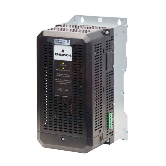
8: 5 V / 5 VDC optional for the RS485 communication 9: 24 V / N/A Service port for updating software with a special tool Power LED (green) Fault LED (red) Table 6: Terminals and LED's Figure 2: EV3150B, EV3185B, side and front views AGL_Sol_EV3_E_Rev_02... -
Page 10: Mounting
Mounting The drive should be located as close to the compressor as possible, preferably within 1 metre of the compressor. To avoid electromagnetic interference please ensure that the motor cables do not cross or attach to any other connecting cables. There should be at least a natural air stream inside the cabinet and around the drive to keep the temperature below 60 °C. -
Page 11: Electrical Installation
DLT-sensor, high-pressure limiter and the RS485 serial communication (Modbus) to the drive. Figure 4: Wiring EV3150B, EV3185B 3.4.3 DC chokes The integrated DC choke has protection class IP00 and temperature class H. The choke is positioned between the heatsink of the drive and the drilled metal sheet, within the lower metal case. -
Page 12: Compressor Connection
Drive model / choke breaker (A) section (mm²) current (A) reduce EMC noise @ 30 °C @ 60 °C ambient EV3150B 1 x H63x38-25 KH10 1 x DC choke Type B (3 turns) EV3185B 1 x H63x38-25 KH10 1 x DC choke... -
Page 13: Dlt Input
▪ Powered by: Internal 5 VDC (terminal 2) ▪ Temp. range: -40 to +150 °C ▪ Reference: Emerson TP1 series The sensor should be mounted on the discharge line approx. 120 mm away from the compressor outlet. After starting the compressor, the drive observes the temperature from the DLT sensor. The observable temperature range is between -40 and 150 °C. -
Page 14: Start-Up & Operation
Furthermore, it provides an advanced register description. For the latest version of the Modbus map, please contact the Application Engineering department at Emerson. Drive configuration The EV3 drives were specially designed for the ZPV066/096 and YPV066/096 compressors. The compressor code will be set by default, so it will not have to be introduced by the user. -
Page 15: Envelope Control
The power demand must be written in register [102]. The value represents the percentage of power (0 - 100 %). The maximum power that can be commanded on the stator is readable via register [52]. The relation between the power and the value introduced in register [102] is the following: ▪... -
Page 16: Active Envelope Protection
1: High-Speed Envelope Protection ▪ Overload Protection enabled. ▪ Normal Operation: the minimum speed is the minimum speed of the envelope. Value taken from the EEPROM and updated frequently based on the operating point. The user must take care to run the compressor within the envelope at all times. -
Page 17: Clearing Faults
Grey zone: ▪ Speed range: 2600-6000 rpm ▪ Allowed running time based on the evaporating temperature: o if less than -15 °C: 15 minutes o if more than -15 °C: 30 minutes If the speed demand is less than 2600 rpm or more than 6000 rpm, the speed is increased or decreased automatically to respect the speed range. -
Page 18: Compressor Shutdown
Figure 7: Start-up sequence Compressor shutdown The user has the possibility to perform an immediate shutdown or a controlled shutdown. By setting the compressor Enable register [100] to Disabled, while the speed demand is greater than 0, the drive will perform an immediate stop. Otherwise if the user sends a Disable command as well as 0 speed demand (insert 0 in Compressor Speed Demand register [101]), the drive will issue a controlled stop. -
Page 19: Optional Analog Board
Optional analog board The analog board is foreseen for users who do not have the possibility to control the EV3 drive via an RS485 communication and the Modbus protocol. To control the EV3 drive the analog board needs a digital-enable signal and an analog signal to set the speed or heating demand. The drive compressor package must be selected by a 6-digit DIP-switch. -
Page 20: Control And Configuration
Code Description and comments Programming port: ▪ Used for software updates via Renesas Emulators together with a special PCB board from Emerson Status LED (green): ▪ Flashing fast: Fault state ▪ Flashing slow: Standby ▪ Constantly on: Compressor running / heating... -
Page 21: Clearing Faults
Figure 10: Analog control board code selection NOTE: The binary code represents the binary transformation of the package code starting from right to left (from 6 to 1). 5.2.2 Clearing faults Faults are cleared automatically as long as the cause of the fault is no longer existing. In case of a drive fault the analog board will automatically send the clear fault command to the drive. -
Page 22: Shutdown Conditions
Based on the compressor envelope and the speed range selection (see paragraph 5.2.7 "Compressor speed range selection") it can happen that low speed demands will be ignored. 5.2.6 Shutdown conditions The drive will stop in heating as well as in running mode if one of below conditions occurs: ▪... -
Page 23: Protections And Alerts
Protections and alerts When the drive is in normal operation, the power LED will always be turned on and the fault LED will be off. In case the drive is in fault or protection mode, the fault LED will flash at 2 Hz for a specific number of times. -
Page 24: Power Module Speed-Drop Protection
Reasons for moving to Speed-Drop Protection mode: ▪ Overtemperature of the power module ▪ Overtemperature in the discharge line ▪ Operating in field weakening range ▪ Output overcurrent ▪ Input overcurrent ▪ Drive ambient temperature foldback The controller can avoid moving to the Speed-Drop Protection mode by using registers [37], [39], [40], [41], [42] and [46] for control purposes. -
Page 25: Speed Drop Protection Limits, Led And Analog Board Codes
18 Envelope timeout Speed-drop protection limit / Module temperature Compressor recovery value 81.3 foldback timeout speed drop EV3150B, EV3185B: 108 °C / 103 °C Speed-drop protection limit / Input current foldback recovery value Compressor 81.4 timeout EV3150B: 30 A / 28 A... - Page 26 Read from EEPROM 84.9 SW overcurrent trip Compressor W phase Compressor Read from EEPROM 84.10 SW overcurrent trip EV3150B: 28 A RMS Compressor 27 Compressor overload 84.15 EV3185B: 39 A RMS trip Compressor loss U phase Compressor loss V phase...
-
Page 27: Maintenance & Repair
The fan is connected with a lock-type connector to the main board of the drive. Press the plastic clip of the connector and disconnect the fan. Connect the new fan and reassemble the unit. The replacement fan model is supplied by Emerson under ident number 8421949. AGL_Sol_EV3_E_Rev_02... -
Page 28: Frequently Asked Questions
Check if the fan is on and working properly. If Limit / recovery the fan is broken, the module will overheat, and Drive module EV3150B: 110 °C / 85 °C Compressor trip 80.11 the drive will report this error. overtemperature EV3185B: 110 °C / 85 °C... - Page 29 Compressor 81.4 triggered if the load is too high for a certain timeout EV3150B: 30 A / 28 A speed drop speed during 30 seconds. EV3185B: 41 A / 39 A This fault will be triggered if the fan stops working.
- Page 30 When the EV3 drive is commanded by one of the Emerson controllers, this functionality is disabled. When the EV3 drive is running in a unit without Emerson controller this functionality is enabled by default.
-
Page 31: Appendix 1: Drive Dimensions And Mounting Instructions (Ev3150B / Ev3185B)
Appendix 1: Drive dimensions and mounting instructions (EV3150B / EV3185B) AGL_Sol_EV3_E_Rev_02... -
Page 32: Appendix 2: Choke Dimensions
Appendix 2: Choke dimensions Figure 14: DC choke 40A, 2mH for EV3150B Figure 15: DC choke 50A, 2mH for EV3185B AGL_Sol_EV3_E_Rev_02... -
Page 33: Appendix 3: Analog Control Board Description And Dimensions
Appendix 3: Analog control board description and dimensions Figure 16 AGL_Sol_EV3_E_Rev_02... -
Page 34: Appendix 4: Envelopes
Appendix 4: Envelopes Figure 17: ZPV066* compressor envelope with R410A (20 °F SH, 15 °F SC, 95 °F ambient) Figure 18: ZPV096* compressor envelope with R410A (20 °F SH, 15 °F SC, 95 °F ambient) AGL_Sol_EV3_E_Rev_02... -
Page 35: Appendix 5: Advanced User Interface
3. Emerson does not assume responsibility for the selection, use or maintenance of any product. Responsibility for proper selection, use and maintenance of any Emerson product remains solely with the purchaser or end user. - Page 36 The Emerson logo is a trademark and service mark of Emerson Electric Co. Emerson Climate Technologies Inc. is a subsidiary of Emerson Electric Co. Copeland is a registered trademark and Copeland Scroll is a trademark of Emerson Climate Technologies Inc.. All other trademarks are property of their respective owners.
Need help?
Do you have a question about the EV3150B and is the answer not in the manual?
Questions and answers