Table of Contents
Advertisement
©2021 Lennox Industries Inc.
Dallas, Texas, USA
THIS MANUAL MUST BE LEFT WITH THE
HOMEOWNER FOR FUTURE REFERENCE
WARNING
Improper installation, adjustment, alteration, service
or maintenance can cause property damage, personal
injury or loss of life. Installation and service must be
performed by a licensed professional HVAC installer or
equivalent, service agency, or the gas supplier.
IMPORTANT
The Clean Air Act of 1990 bans the intentional venting of
refrigerant (CFCs, HCFCs and HFCs) as of July 1, 1992.
Approved methods of recovery, recycling or reclaiming
must be followed. Fines and/or incarceration may be
levied for noncompliance.
CAUTION
As with any mechanical equipment, contact with sharp
sheet metal edges can result in personal injury. Take
care while handling this equipment and wear gloves and
protective clothing.
INSTALLATION
INSTRUCTIONS
Merit
Series
®
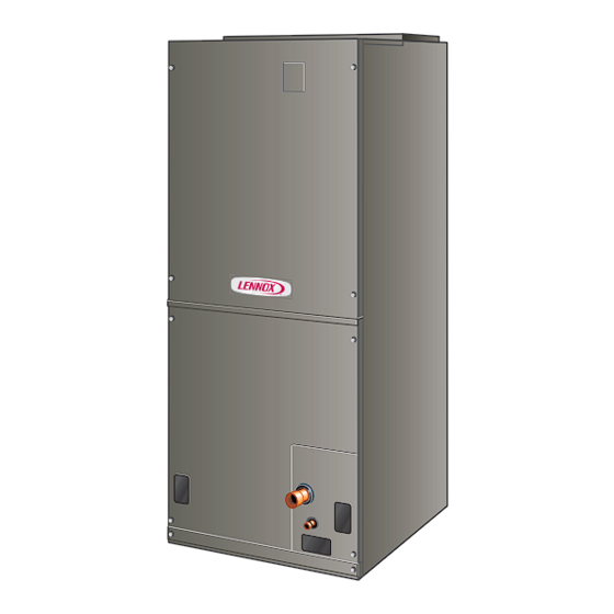
CBA25UHV Air Handler Units
MULTI-POSITION AIR HANDLERS
507775-02
2/2021
Table of Contents
Requirements ................................................................3
Installation Clearances ..................................................3
Installation .....................................................................4
Condensate Drain...........................................................7
Duct System and Filters ...............................................8
Brazing Refrigerant Lines ..............................................9
Sealing the Unit ...........................................................12
Electrical Connections .................................................12
BDC3 Blower Control ..................................................16
Adjusting the Blower Speed ........................................16
Check-out Procedures .................................................21
Maintenance ................................................................21
Repairing or Replacing Cabinet Insulation ..................21
Professional Maintenance ...........................................22
Use of Air Handler During Construction .......................22
Shipping and Packing List
Package 1 of 1 contains:
1 - Assembled air handler unit factory-equipped for upflow
or horizontal air discharge application (includes upflow
and horizontal drain pans and preinstalled air filter).
Check the air handler for shipping damage; if found, im-
mediately contact the last carrier. Check the unit rating
plate to confirm that delivered unit matches order.
General Information
The CBA25UHV series air handler with all-aluminum
coil is designed for indoor installation only. As shipped,
the unit is ready for installation in either upflow or horizon-
tal right-hand air discharge applications. Horizontal drain
pan may be repositioned in the field to allow installation
in the horizontal left-hand air discharge position. Various
accessories are available and listed in the CBA25UHV
Product Specification bulletin (EHB) for ordering.
This instruction is intended as a general guide and does
not supersede local or national codes in any way. Consult
authorities having jurisdiction before installation.
IMPORTANT: Special procedures are required for clean-
ing the all-aluminum coil in this unit. See page 22 in this
instruction for information.
Page 1
Advertisement
Table of Contents

Related Manuals for Lennox CBA25UHV


Summary of Contents for Lennox CBA25UHV
-
Page 1: Table Of Contents
Dallas, Texas, USA CBA25UHV Air Handler Units MULTI-POSITION AIR HANDLERS 507775-02 2/2021 Table of Contents CBA25UHV Unit Dimensions – Upflow – Inches (mm) ..2 Requirements ..............3 Installation Clearances ..........3 Installation ..............4 Condensate Drain............7 Duct System and Filters ..........8 Brazing Refrigerant Lines ..........9 Sealing the Unit ............12... -
Page 2: Cba25Uhv Unit Dimensions - Upflow - Inches (Mm)
CBA25UHV Unit Dimensions – Upflow – Inches (mm) 1 (25) DETAIL OF PIPING PLATE 4-3/4 3/4 (19) (121) SUCTION LINE SUPPLY AIR LIQUID OPENING CONDENSATE LINE 14-1/2 DRAINS (2) (368) 2-3/8 (Horizontal) (60) 1 (25) 1 (25) CONDENSATE DRAINS (2) -
Page 3: Requirements
When the unit is installed in varying capacities. These units must be installed as a an unconditioned space, apply sealant around electrical part of a matched system as outlined in the CBA25UHV wires, refrigerant piping and condensate lines at the Product Specification bulletin (EHB). -
Page 4: Installation
Louvers or return air grilles are field-supplied. Local codes may limit application of systems without a ducted return to single-story buildings. When a CBA25UHV unit is installed in a closet with a lou- vered return opening, the minimum open area for the lou- vers will be: •... - Page 5 5 - If the unit is suspended, the entire length of the TOP CAP ROTATED TO cabinet must be supported. If you use a chain or CORRECT POSITION strap, use a piece of angle iron or sheet metal TOP CAP SCREWS CABINET attached to the unit (either above or below) to SUPPORT...
- Page 6 If electric heat section with circuit breakers (ECBA25) is to the unit (either above or below) so that the full installed in a CBA25UHV unit in a downflow application, length of the cabinet is supported. Use securing the circuit breakers must be rotated 180° to the UP screws no longer than 1/2ʺ...
-
Page 7: Condensate Drain
METERS) LENNOX P-TRAP 49P66 REQUIRES A LARGER INSTALLATION SPACE THAN THE J-TRAP 91P90. PIPE NIPPLE PROVIDED IN BAG ASSEMBLY - SCH 80, 3/4” I. D. X 5” - 34K7401 (1): CUT THE PIPE IN HALF AND USE IT TO ROUTE THE MA IN DRAIN. -
Page 8: Duct System And Filters
Confirm primary and secondary drains are open. 2 - Check the installed drain pan. Drain pan must be 1 - CBA25UHV units are equipped with a drain pan, draining completely. Drain line fittings must not be which includes green (main drain) and red (secondary leaking. -
Page 9: Brazing Refrigerant Lines
INSTALLING DUCT SYSTEM WARNING Connect supply air duct to the flange on top of the air han- dler. If an isolation connector is used, it must be nonflam- Polyol ester (POE) oils used with HFC-410A refrigerant mable. absorb moisture very quickly. It is very important that the refrigerant system be kept closed as much as possible. - Page 10 Technical Support Product Applications for assistance. 5 - Braze using an alloy of silver or copper and To obtain the correct information from Lennox, be sure to phosphorus with a melting point above 1,100°F communicate the following information: Model and capac- (593°C).
- Page 11 PLEASE READ IMPORTANT ISSUES CONCERNING BRAZING OPERATIONS ON PREVIOUS PAGES BEFORE PROCEEDING. NOTE - REFER TO OUTDOOR UNIT INSTALLATION INSTRUCTIONS FOR REFRIGERANT PIPING SIZE REQUIREMENTS. NOTE - Use silver alloy brazing rods with five or six percent minimum silver alloy for copper-to-copper brazing, 45 percent alloy for copper-to-brass and copper-to-steel brazing.
-
Page 12: Sealing The Unit
WARNING Sealing the Unit Seal the unit so that warm air is not allowed into the cabi- Electric Shock Hazard. net. Warm air introduces moisture, which results in water Can cause injury or death. blow-off problems. This is especially important when the Foil-faced insulation conductive... - Page 13 4 - Use UL-listed wire nuts to connect the field supply 208 VOLT CONVERSION conductors to the unit black and yellow leads, and 1 - Disconnect all power supplies. the ground wire to ground terminal marked GND. 2 - Remove the air handler access panel. 5 - 5.
- Page 14 FIGURE 14. Typical Wiring Diagram – CBA25UHV Air Handler with Electric Heat – (Variable-Speed Motor) Page 14...
- Page 15 WARNING USE COPPER CONDUCTORS ONLY FIGURE 15. Low Voltage Connections (Variable-Speed Motor) Page 15...
-
Page 16: Bdc3 Blower Control
Merit ® 24V ACCESSORY SERVICE CONTACTS – CBA25UHV. When matched with other sizes, it is rec- RATED FOR 1 AMP 24V/1A ommended that the CFM be adjusted to provide approxi- OR LESS mately 400 CFM per ton. - Page 17 NOTES - The effect of static pressure, filter and electric heater resistance is included in the air volumes listed. First stage cooling air volume is 70% of COOL speed setting. Continuous blower speed is approximately 50% of COOL speed setting. Lennox Harmony III™ Zoning System applications - minimum blower speed is 250 cfm. TABLE 4...
- Page 18 NOTES - The effect of static pressure, filter and electric heater resistance is included in the air volumes listed. First stage cooling air volume is 70% of COOL speed setting. Continuous blower speed is approximately 50% of COOL speed setting. Lennox Harmony III™ Zoning System applications - minimum blower speed is 250 cfm. TABLE 6...
- Page 19 NOTES - The effect of static pressure, filter and electric heater resistance is included in the air volumes listed. First stage cooling air volume is 70% of COOL speed setting. Continuous blower speed is approximately 50% of COOL speed setting. Lennox Harmony III™ Zoning System applications - minimum blower speed is 450 cfm. TABLE 9...
- Page 20 TABLE 11. CBA25UHV Thermostat and Two-Stage Outdoor Unit Operating Sequence Operating Sequence System Demand System Response Thermostat Demand Relative Humidity Handler System Step Status (COOL) Comments Condition pressor NO CALL FOR DEHUMIDIFICATION Normal Operation Acceptable 24 VAC - Y1 Compressor and indoor air handler follow...
-
Page 21: Check-Out Procedures
#4 Pins Jumpered • Set the thermostat 5ºF higher than the indoor tempera- ture. The indoor blower and outdoor unit should cycle A- Motor ramps up to 82%. off. B- Motor then runs at 82% for approximately 7-1/2 min- utes. If demand has not been satisfied after 7-1/2 min- CHECK ELECTRIC HEAT (IF USED) utes, •... -
Page 22: Professional Maintenance
Areas of condensation on the cabinet surface are an indi- cation that the insulation is in need of repair. Lennox does not recommend the use of its air handler unit during any phase of construction. Very low return air tem-... - Page 23 Installing Contractor’s Name_______________________ Installing Date_______________________________ Installing Contractor’s Phone_______________________ Air Handler Model #___________________________ Job Address____________________________________ Thermostat Line Voltage SUPPLY Disconnect Switch Integrated Control Temperature Duct Blower Motor Amps System Electric Heat Amps Duct Static RETURN Filter Drain Line DUCT SYSTEM TOTAL EXTERNAL STATIC (dry coil) dry coil wet coil SUPPLY AIR DUCT...
- Page 24 Installing Contractor’s Name_______________________ Installing Date_______________________________ Installing Contractor’s Phone_______________________ Air Handler Model #___________________________ Job Address____________________________________ Line Voltage Disconnect Switch Thermostat Integrated Control Duct System Duct System Filter RETURN SUPPLY Electric Heat Amps Blower motor Amps Drain Line Duct Static Temperature DUCT SYSTEM TOTAL EXTERNAL STATIC (dry coil) dry coil wet coil...
Need help?
Do you have a question about the CBA25UHV and is the answer not in the manual?
Questions and answers
Can i run the CBA25UHV-048 with the cooling jumper on 2 instead of 3 (default) System runs fine but is loud.