Table of Contents
Advertisement
I N S T R U CT I O N M A N UA L
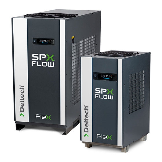
FLEX Series
Refrigerated Type Compressed Air Dryers
Models: DFX 1.1, DFX 1.2, DFX 1.5, DFX 2.1, DFX 3.1, DFX 4.1, DFX 4.5, DFX 5.5
F O R M N O . : 7 4 4 0 0 6 3
R E V I S I O N : 0 6 / 2 0 1 7
R E A D A N D U N D E R S TA N D T H I S M A N UA L P R I O R TO O P E R AT I N G O R S E R V I C I N G T H I S P R O D U CT.
Advertisement
Table of Contents

Related Manuals for SPX FLOW Deltech FLEX Series


Summary of Contents for SPX FLOW Deltech FLEX Series
- Page 1 I N S T R U CT I O N M A N UA L FLEX Series Refrigerated Type Compressed Air Dryers Models: DFX 1.1, DFX 1.2, DFX 1.5, DFX 2.1, DFX 3.1, DFX 4.1, DFX 4.5, DFX 5.5 F O R M N O . : 7 4 4 0 0 6 3 R E V I S I O N : 0 6 / 2 0 1 7 R E A D A N D U N D E R S TA N D T H I S M A N UA L P R I O R TO O P E R AT I N G O R S E R V I C I N G T H I S P R O D U CT.
-
Page 2: Table Of Contents
Contents INTRODUCTION ....................1 SAFETY ........................ 1 INSTALLATION ...................... 1 HOW IT WORKS ....................3 OPTI-ECO CONTROLLER ..................4 START-UP/OPERATION ..................5 MAINTENANCE ....................6 FIELD SERVICE GUIDE ..................7 ENGINEERING DATA .................... 8, 9 DRAWINGS General Arrangement Model: DFX 1.1 ................... 10 Model: DFX 1.2 ................... -
Page 3: Introduction
INTRODUCTION Carefully read the following safety rules before proceed- ing with installation, operation or maintenance. The rules Compressed air is generated by compressing atmospheric air are essential to ensure safe dryer operation. Failure to of which contains moisture and other containments, into high follow these rules may void the warranty or result in dryer pressure air. - Page 4 Ambient Air Temperature Drains Locate the dryer indoors where the ambient air temperature will Condensate must be drained from the dryer to prevent an influx be between 39°F (4°C) and 122°F (50°C). Intermittent operation into outlet air. The FLEX dryers are equipped with an automatic at ambient temperatures up to 122°F (50°C) will not damage the no loss drain valve and internal drain hoses up to the drain dryer but may result in a higher dew point or dryer shutdown...
-
Page 5: How It Works
Electrical Connections HOW IT WORKS Phase Change Mechanism of the FLEX Dryer Operation of dryers with improper line voltage constitutes abuse and could affect the dryer warranty. When the refrigeration compressor and the condenser fan The dryers are constructed according to NEMA Type 1 electrical are running, the cold refrigerant in the chiller (evaporator) standards. -
Page 6: Opti-Eco Controller
OPTi-ECO CONTROLLER Additional functions (Level 2) Save the operating data a. Refrigerant compressor on/off status, Alarm, Dew There are two kinds of OPTi-Eco Controller, the Level 1 has point level, Inlet air temperature basic functions while the Level 2 has advanced functions like b. -
Page 7: Start-Up/Operation
START-UP/OPERATION Confirm that the condensate lines from the drain valve discharge into a collection tank or an environmentally approved disposal system. The FLEX dryer is designed to run and stop repeatedly. Let the Never use the disconnect switch to shut down the dryer FLEX dryer operate even when the demand for compressed air for an extended period of time (except for repair). -
Page 8: Maintenance
MAINTENANCE Models: DFX 1.1, DFX 1.2, DFX 1.5, DFX 2.1, DFX 3.1, DFX 4.1 The FLEX Dryer requires little maintenance for satisfactory opera- tion. Good dryer performance can be expected if the following routine maintenance steps are taken. Head General Bowl O-Ring For continued good performance of your refrigerated dryer, all refrigeration system maintenance should be performed by... -
Page 9: Field Service Guide
FIELD SERVICE GUIDE PROBLEM SYMPTOM POSSIBLE CAUSE REMEDY Water downstream of No discharge from no loss drain Drain valve failure or accumulation Dismantle drain valve: clean, repair or replace. dryer. valves. of dirt in drain valve strainer. See maintenance section. Inlet air temperature is too high. -
Page 10: Engineering Data
ENGINEERING DATA SPECIFICATIONS Dimensions - inches (mm) Rated Capacity Inlet /Outlet Net Weight MODEL (scfm) Connections lbs (kg) Height Width Length 29.6 14.3 23.7 DFX 1.1 NPT 1” (751) (363) (603) (54.5) 28.0 14.3 30.7 DFX 1.2 NPT 1” (711) (363) (781) (66.5) - Page 11 ENGINEERING DATA MINIMUM - MAXIMUM OPERATING CONDITIONS ALL MODELS Min.-Max. Inlet Air Pressure (compressed air at inlet to dryer) 43.5 - 232 psig (3 - 16 bar) Min.-Max. Inlet Air Temperature (compressed air at inlet to dryer) 39°F - 122°F (4°C - 50°C) Min.-Max.
-
Page 12: Model: Dfx 1.1
DRAWINGS: GENERAL ARRANGEMENT Figure 5A Model: DFX 1.1 DIMENSIONS, INCHES (MM) INLET/OUTLET WEIGHT MODEL CONNECTIONS Lb. (kg) 4.69 4.97 8.41 19.20 14.27 29.58 12.75 23.72 3.39 15.40 22.14 DFX 1.1 1" NPT (119) (126.2) (213.5) (487.7) (362.4) (751.2) (324) (602.5) (86.2) (391.2) (562.4) -
Page 13: Model: Dfx 1.2
DRAWINGS: GENERAL ARRANGEMENT Figure 5B Model: DFX 1.2 DIMENSIONS, INCHES (MM) INLET/OUTLET WEIGHT MODEL CONNECTIONS Lb. (kg) 3.41 4.97 6.77 19.25 14.29 12.76 30.76 5.56 19.29 29.18 DFX 1.2 1" NPT (86.5) (126.2) (172) (489.2) (363) (711.2) (324) (781.3) (141.2) (490) (741.2) (66.5) -
Page 14: Models: Dfx 1.5, Dfx 2.1
DRAWINGS: GENERAL ARRANGEMENT Figure 5C Models: DFX 1.5, DFX 2.1 DIMENSIONS, INCHES (MM) INLET/OUTLET WEIGHT MODEL CONNECTIONS Lb. (kg) 4.86 7.86 3.63 24.38 17.44 29.97 15.91 35.50 3.39 27.16 33.91 188.5 DFX 1.5 2" NPT (123.5) (199.6) (92) (619.2) (443) (761.2) (404) (901.3) -
Page 15: Models: Dfx 3.1, Dfx 4.1
DRAWINGS: GENERAL ARRANGEMENT Figure 5D Models: DFX 3.1, DFX 4.1 DIMENSIONS, INCHES (MM) INLET/OUTLET WEIGHT MODEL CONNECTIONS Lb. (kg) 4.86 7.86 8.31 25.59 19.41 35.88 17.88 43.75 3.39 35.43 42.17 DFX 3.1 2" NPT (123.5) (199.6) (211.2) (650) (493) (911.2) (454) (1111.3) (86.2) -
Page 16: Models: Dfx 4.5, Dfx 5.5
DRAWINGS: GENERAL ARRANGEMENT Figure 5E Models: DFX 4.5, DFX 5.5 DIMENSIONS, INCHES (MM) INLET/OUTLET WEIGHT MODEL CONNECTIONS Lb. (kg) 4.87 8.58 9.79 30.83 19.43 40.61 17.72 19.30 1.97 43.70 47.64 49.32 DFX 4.5 2" NPT (123.8) (218) (248.6) (783) (493.5) (1031.6) (450) (490) -
Page 17: Models: Dfx 1.1, Dfx 1.2 (115V/1Ph/60Hz)
DRAWINGS: ELECTRICAL SCHEMATIC Figure 6A Models: DFX 1.1, DFX 1.2 (115V/1PH/60Hz) N.C. COM. N.O. -
Page 18: Models: Dfx 1.5, Dfx 2.1, Dfx 4.1 (230V/1Ph/60Hz)
DRAWINGS: ELECTRICAL SCHEMATIC Figure 6B Models: DFX 1.5, DFX 2.1, DFX 4.1 (230V/1Ph/60Hz) RS485 - RS485 + RS232 TX RS232 RX N.C. COM. N.O. -
Page 19: Models: Dfx 3.1, Dfx 4.5, Dfx 5.5 (460V/3Ph/60Hz)
DRAWINGS: ELECTRICAL SCHEMATIC Figure 6C Models: DFX 3.1, DFX 4.5, DFX 5.5 (460V/3Ph/60Hz) RS485 - RS485 + RS232 TX RS232 RX N.C. COM. N.O. -
Page 20: Air And Refrigerant Flow Schematic
DRAWINGS: AIR AND REFRIGERANT FLOW SCHEMATIC Figure 7 Models: DFX 1.1, DFX 1.2, DFX 1.5, DFX 2.1, DFX 3.1, DFX 4.1, DFX 4.5, DFX 5.5 MOISTURE SEPARATOR INTEGRATED TEMP. SENSOR3 (DFX1.5~5.5 ONLY) BRAZED PLATE HEAT EXCHANGER <REF-PCM-AIR> <AIR-AIR> WETTED AIR INLET DRIED AIR OUTLET CAPILLARY TUBE MANUAL VALVE... -
Page 21: Replacement Parts
REPLACEMENT PARTS Model: DFX 1.1 Models: DFX 1.2, DFX 1.5, DFX 2.1, DFX 3.1, DFX 4.1, FLEX 1.2 - FLEX 5.1 DFX 4.5, DFX 5.5 FLEX 1.1 16 12 8 18 16 15 13 12 8 FLEX 1.2 - FLEX 5.1 DFX 1.1 DFX 1.2 DFX 1.5... -
Page 22: Maintenance Kits
MAINTENANCE KITS Model Kit Components DFX 1.1 DFX 1.2 DFX 1.5 DFX 2.1 DFXMK DFXMK DFXMK DFXMK No Loss Drain Valve Repair Kit, Standard Kit Drain Cover (7461666) (7461666) (7461666) (7461666) No Loss Drain Valve Repair Kit, Standard Kit DFX1.1-FPMK DFX1.2-FPMK DFX1.5-FPMK DFX2.1-FPMK... -
Page 23: Warranty
WARRANTY The manufacturer warrants the product manufactured by it, when properly installed, operated, applied, and maintained in accordance with procedures and recommendations outlined in manufacturer’s instruction manuals, to be free from defects in material or workmanship for a period as specified below, provided such defect is discovered and brought to the manufacturer’s attention within the aforesaid warranty period. - Page 24 4647 S.W. 40th Avenue Ocala, Florida 34474-5788 U.S.A. P: (724) 745-8647 F: (724) 745-4967 E: deltech.americas@spxflow.com www.spxflow.com/deltech Improvements and research are continuous at SPX FLOW, Inc. Specifications may change without notice. ISSUED 06/2017 Form No.: 7440063 Revision: D COPYRIGHT ©2017 SPX FLOW, Inc.
Need help?
Do you have a question about the Deltech FLEX Series and is the answer not in the manual?
Questions and answers