Table of Contents
Advertisement
Quick Links
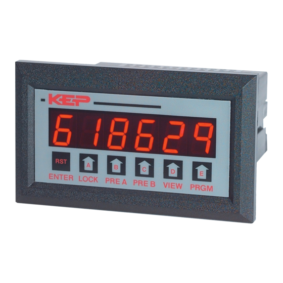
Description:
The MS287 is a special version of our Minitrol series counter/
ratemeter.
The standard Minitrol is modified to bring a 60Hz
(50Hz) signal to pin 10 (AC powered units only). The user has the
option of connecting this signal to the A input, B input or both. By
entering the proper scaling factor, the user can scale the input to
read the desired time base. EXAMPLE: If the unit is powered with
115VAC @ 60Hz, The scaling factor for A can be set to yield
different time bases: i.e. 60 yields seconds, 360 yields minutes & 1/
10, 3600 yields minutes, etc. Input B can be scaled the same way
or used as a separate counter.
special can be used in many applications involving time/count
control.
To order this special, add the prefix "MS287" to the
standard Minitrol part number, i.e. MS287MC2A3.
ORDERING NUMBER
EXAMPLE:
MS287
MC2
SPECIAL
TYPE
MRT= 6 digits, counter / ratemeter
with presets and scaling.
MC2= 6 digits, counter only with
presets and scaling.
OPERATING VOLTAGE
A= 110 VAC ± 15% or 11 to 15 VDC
B= 220 VAC ± 15% or 11 to 15 VDC
C= 24 VAC ± 15% or 11 to 15 VDC
COUNT INPUTS
3= Standard, 4-30 VDC Accepts simultaneous inputs.
OPTIONS
1= RS232 Communications
2= RS422 Communications
A= Analog Output (4-20/0-20 mA)
Accessories
Separate non keyboard panel order #34235
Separate keyboard panel - order #34237
MS287 INSTRUCTIONS
MINITROL WITH LINE FREQUENCY TIME BASE
With a little imagination, this
A
3
KESSLER-ELLIS PRODUCTS 10 Industrial Way East, Eatontown NJ 07724
800-631-2165 • 732-935-1320 • Fax 732-935-9344 • http://www.kep.com
Application:
This product special is especially useful for combined counter and
timer control functions. It has been used in applications such as
controlling the lubrication of a gear box in a drilling machine. The
gear box has to be lubricated for 5 seconds every 10 minutes. The
lubricating fluid needs to be changed after 75,000 lubrications.
This is easily accomplished using the MS287MC2A3.
The unit is programmed as follows:
Factor: factor of A = 3600, factor of B = 1.
Count: rst 0 (reset to 0), A sep B (A & B are separate counters), Hi
CPS (0-10KHz input speed).
Relay: A = 5.0 (duration of A relay is 5 seconds), B = 0.0 (duration
of B relay is latched till reset).
Presets: Preset A = 10, Preset B = 75,000
The relay on the machine which is energized when the machine is
running is connected between pin 10 (60Hz) and pin 5 (input A). A
simple solder jumper modification is made on the PC board to
make B a "batch" counter. Counter B will advance once for each
output of A. Relay A is connected to a solenoid valve which
controls the lubricating fluid. 115VAC/60Hz is connected to pins 11
& 12.
1
This system operates as follows:
When the machine is running, the relay on the machine is ener-
gized and the A counter starts to accumulate time. When the A
counter (timer) reaches 10 (preset A), the A counter resets, the A
Relay energizes and opens the solenoid valve for 5 seconds and
the B counter advances one. The system will run this cycle until
the B counter reaches 75,000.
75,000, the B Relay energizes and turns on a light to signal that the
fluid needs to be changed.
SOLENOID
VALVE
To 115 VAC
LIGHT
COM.
N.O
N.C
When the B counter reaches
To 115 VAC
MOV
Recommended
1- COMMON
2- N.O.(N.C./NPN)
3- COMMON
4- N.O.(N.C./NPN)
5- A INPUT
6- B INPUT
7- 12VDC OUT/+DC IN
8- -DC (GROUND)
9- RESET INPUT
10- 60Hz 15V OUT
11- A.C. INPUT
12- A.C. INPUT
99367 7/3/97
Advertisement
Table of Contents

Related Manuals for Kessler-Ellis Products MINItrol Series


Summary of Contents for Kessler-Ellis Products MINItrol Series
- Page 1 MS287 INSTRUCTIONS MINITROL WITH LINE FREQUENCY TIME BASE Description: Application: The MS287 is a special version of our Minitrol series counter/ This product special is especially useful for combined counter and ratemeter. The standard Minitrol is modified to bring a 60Hz timer control functions.
- Page 2 MODELS MINItrol SERIES INSTALLATION & OPERATING INSTRUCTIONS KESSLER-ELLIS PRODUCTS 10 Industrial Way East Eatontown, NJ 07724 800-631-2165 • 732-935-1320 Fax: 732-935-9344 99306 08/17/15...
- Page 3 Publication of this information does not convey any rights to use or reproduce it or to use for any purpose other than in connection with the installation, operation and maintenance of the equipment described herein. Copyright 1989, Kessler-Ellis Products Co. Printed in USA. All Rights Reserved. WARNING This instrument contains electronic components that are susceptible to damage by static electricity.
-
Page 4: Table Of Contents
TABLE OF CONTENTS SPECIFICATIONS ....................1 DECODING PART NUMBER .................. 2 HOW TO MOUNT THE UNIT .................. 3 WIRING MINITROL ....................4 UP/DOWN CONTROL AND QUADRATURE INPUTS ..........4 WHAT CAN YOU VIEW ................... 6 OUTPUT JUMPER SELECTIONS ................6 MILLIVOLT INPUT OPTION JUMPER SELECTIONS .......... -
Page 6: Specifications
An optional 4-20mA (0-20mA) output is available for 250 mA DC max. or 6.5 VA AC the Minitrol series. The output can be programmed OUTPUT POWER (AC powered units only) to track rate or total. This feature is available by +12 VDC @ 50 mA, unregulated -10 + 50% adding suffix A to the part number. -
Page 7: Decoding Part Number
SPECIFICATIONS DECODING PART NUMBER (continued) RS232/RS422SERIAL INTERFACE MINItrol (MRT, MC2, MR2) If the serial interface option is supplied, up to 99 units can be linked together. (The terminal addressing the unit must be capable of Example: driving all loads in the loop.) Unit status and new set points can be Series: communicated by serial communication. -
Page 8: How To Mount The Unit
HOW TO MOUNT THE UNIT The unit is designed to be mounted with a gasket providing a water tight seal. Two mounting brackets are provided to secure the unit to the panel. A panel less than .1" may distort if the clamps are screwed too tightly. Slide the body of the unit through the rubber gasket. -
Page 9: Wiring Minitrol
WIRING MINITROL The rear terminal contains 12 screw terminals for connecting #14 to #28 gauge wire. The unit is controlled by a microprocessor and, therefore, an electrically "noisy" environment could cause operating problems. The input power line should not be common to power lines for motors, pumps, contactors, etc. The unit is designed to be immune from line or RF voltage interference. - Page 10 CONNECTING AC / DC POWER NOTE: Connect power only after other connections are finished. Do not touch the live AC power terminals! The unit has been designed with an isolated AC input. Thus, polarity is not a concern for the AC input. The chassis is plastic, therefore earth ground is not used.
-
Page 11: What Can You View
WHAT CAN YOU VIEW? 1) "A sub B" - If you have selected the "A sub B" mode, pressing "view" shows: A) The net result of subtracting input B from input A. Pulses on input B will subtract (count down). Pulses on input A will add (count up) if "reset to 0"... -
Page 12: Operating Front Panel
OPERATING THE FRONT PANEL 6 5 4 3 2 1 ENTER LOCK PRE A PRE B VIEW PRGM Press to enter Press to "reset" Press to cycle Press to Press to Press to alternately lock code for in operating through PROGRAM view or view or view A rate &... -
Page 13: Program Codes & Descriptions
The following is a list of abbreviations as they appear on the display and front panel of the unit. ABBREVIATION DESCRIPTION SCALING FACTOR - For A and B Inputs. Each input has a separate 5 digit dividing scale factor. FACTOR DECIMAL POINT FOR FACTOR A - Enter location of decimal point for scaling Factor A by pressing the DP F A button under the digit where the decimal is desired. -
Page 14: Minitrol Terminations
LOCK - This portion of the menu allows you to: 1) lock the program (presets are still accessible) 2) lock all (presets and program are locked). LOCK PROGRAM - This will lock the program and allow the presets to be changed when the unit is in the LC PRG lock mode. -
Page 15: Calculating Scale Factors
CALCULATING SCALE FACTORS There are two separate dividing scale factors, one for input "A" and one for input "B". The factor to enter is the number of pulses per the desired unit of measurement. The factor ranges from 0.0001 to 99999. The factor is the same for rate and count on input "A". -
Page 16: Minitrol Programming Procedure
PROGRAMMING REMARKS PRESS DISPLAY STEP This section of the menu is used to set up the scaling factors for inputs A & B. factor SETTING SCALING This sets the decimal for factor A. Press FACTORS the arrow key under the digit where dp f a the decimal is desired. -
Page 17: Setting The Counter
PRESS DISPLAY REMARKS factor STEP This section of the menu sets up the counter information. count SETTING Press the PRGM key to choose RST 0 rst 0 COUNTER (reset to 0, count up) or SET PR (set to preset, count down), press the ENTER set pr key to enter the displayed choice. -
Page 18: Setting The Rate
PRESS DISPLAY REMARKS STEP factor SETTING count THE RATE This section of the menu is used to set up rate the rate information. Press the PRGM key to choose RPS (rate per second) or SCALE (RPM, RPH). Press ENTER to enter displayed choice. scale Press PRGM to choose ÷60 (RPM) or z 60... -
Page 19: Setting The Lock Code & Locking The Unit
PRESS DISPLAY REMARKS STEP factor SETTING count LOCK rate This section of the menu is used to set up the lockout type and code. LC PG = Locks program but presets and re- are accessible. LC PG LC ALL= Locks entire keypad. Press the PRGM button to toggle between LC ALL choices;... -
Page 20: Setting The Relays & Presets
PRESS DISPLAY REMARKS factor count STEP rate SETTING RELAYS This section sets up the relay information. relay Press the PRGM key to choose A TOT (A a tot assigned to total) or A RATE (A assigned to rate). Press enter when the desired choice is a rate displayed. -
Page 21: Output Wiring
OUTPUT WIRING The following diagrams detail the connection of the relay and analog output options. Each relay consist of a form A contact (Normally Open). NPN transistor or Normally Closed contacts are available with solder jumpers (see Jumper Options). SOLENOID (Single Stage) Use Relay A (pins 1 &... -
Page 22: Analog Output Option
ANALOG OUTPUT OPTION Description: SWITCH 4: Calibrate (normally off) An optional 4-20mA (0-20mA) output has been added to the Minitrol Switch 4 is used for calibration. Calibration is done at the factory series. The output can be programmed to track rate or total. This and should not be needed (see SWITCH 1 to enter high and low feature is available by adding suffix A to the part number. -
Page 23: Rs232/Rs422 Serial Communications
INTERFACE CARD RS 232/422 OPERATION RS 232/422 SET-UP: PARITY: All serial communication mode changes must be done Parity is a bit of information that is inserted before the stop through serial communications. Mode changes cannot be bit and is used to help check if the transmission is correct. done through the front panel. - Page 24 SERIAL INPUT COMMANDS: The input impedance of RS232 is 3KΩ to 7KΩ worst case. To get a unit on line you must address it by it's device number. The terminal addressing the unit must be capable of driving This is done by typing DXX(S), XX= device number. The unit all loads in the loop.
- Page 25 RS232 / RS422 WIRING RS 232 COMPUTER HOOKUP: RECEIVE PIN (3) RS 232: When connecting the unit to a computer with RS 232 TRANSMIT PIN (2) communication, only three connections are needed. These ENTER LOCK PRE A PRE B VIEW PRGM GROUND PIN (5) connections are: Receive data, Transmit data and Ground.
-
Page 26: Troubleshooting Guide
TROUBLESHOOTING GUIDE PROBLEM POSSIBLE CAUSES SOLUTIONS Power is applied to unit but the display 1. AC or DC power wiring is incorrect. 1. Recheck power wiring does not light. Unit works, but occasionally the display 1. Line noise is affecting the processor 1. -
Page 27: Warranty
NOTE TO OUR CUSTOMER KEP is dedicated to providing complete customer service and customer satisfaction. If you have any comments or criticisms about how to improve this manual, please make a note of the problem/improvement and notify us. We are always open to new ideas and improvements.
Need help?
Do you have a question about the MINItrol Series and is the answer not in the manual?
Questions and answers