Table of Contents
Advertisement
Quick Links
Advertisement
Table of Contents

Related Manuals for Estun E21S


Summary of Contents for Estun E21S
- Page 1 E21S Operation Manual (Version: V1.06)
- Page 2 Revision Record Version Date Description V1.00 2012-06-04 Initial release. V1.01 2013-03-14 The password of entering to SYS PARA page is modified. V1.02 2013-03-27 Revise some expression in this document. V1.03 2014-06-20 Part of interface definition is modified. Parameters CutDelay En. and MaxCut Delay are added on SYS PARA.
-
Page 3: Table Of Contents
E21S Operation Manual Contents Preface............................1 Chapter 1 Product Overview..................... 2 1.1 Product introduction....................2 1.2 Operation panel......................2 1.3 Displayer........................4 Chapter 2 Operation Instruction..................5 2.1 Basic operation procedure..................5 2.2 Programming......................6 2.2.1 Single-step programming..................... 6 2.2.2 Multi-step programming......................8 2.3 Parameter setting.............. -
Page 4: Preface
Copy right is preserved by ESTUN. It is not allowed to add or delete part or all of the manual content without ESTUN’s consent. Do not use part or all of manual content for the third party’s design. -
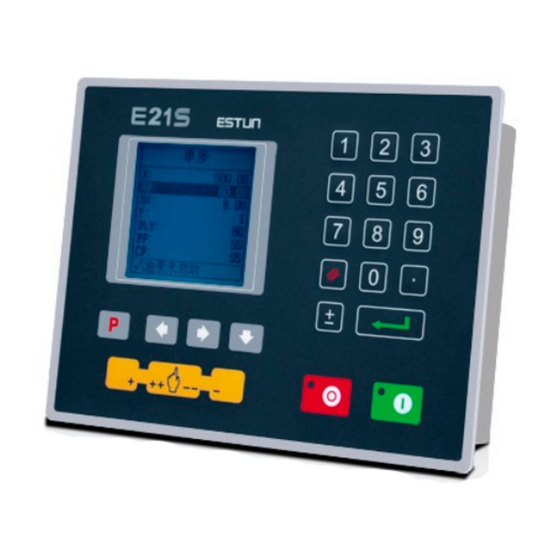
Page 5: Chapter 1 Product Overview
E21S Operation Manual Chapter 1 Product Overview 1.1 Product introduction This product is equipped with the shear machine dedicated numerical control device which is applicable to various users. Based on ensuring work precision, the cost of numerical control shearing machine is reduced significantly. - Page 6 E21S Operation Manual Functions of panel keys are described in Table 1-1. Table 1-1 Description of key functions Function description Delete key: delete all data in input area on left bottom of displayer. Enter key: confirm the input content. If no content is input, the key...
-
Page 7: Displayer
E21S Operation Manual 1.3 Displayer E21S numerical control device adopts 160*160 dot matrix LCD displayer. The display area is shown in Figure 1-2. Figure 1-2 Display area Title bar: display relevant information of current page, such as its name, etc. -
Page 8: Chapter 2 Operation Instruction
E21S Operation Manual Chapter 2 Operation Instruction 2.1 Basic operation procedure Basic switch over and operation procedure of the device is shown in Figure 2-1. Figure 2-1 Basic Operational Flow... -
Page 9: Programming
E21S Operation Manual 2.2 Programming The device has two programming methods, which are single-step programming and multi-step programming. User can set up programming according to actual demand. 2.2.1 Single-step programming Single-step programming is generally used for processing single step to finish work piece processing. - Page 10 E21S Operation Manual Parameter name Unit Range Remarks 0~9.99 In case of single step, delay time for X axis concession. 0~9.99 There is a delay time for the cutter goes to the next work-step, after it leaves the top dead center.
-
Page 11: Multi-Step Programming
E21S Operation Manual Operation steps Operation Step 4 Click , select “DX” parameter, “DLY” parameter, “PP” parameter respectively. Step 5 Set up parameter to 50mm, 2s, 10 by numerical key. Step 6 Click , system execute according to this program. - Page 12 E21S Operation Manual Step 6 In completion of set up, click , enter step parameter set page, as shown in Figure 2-6. Figure 2-6 Step parameter set page Step 7 Click , select step parameter that needs to be set up, input program value, click , and the setup takes effect.
- Page 13 E21S Operation Manual Parameter name Unit Range Remarks mm/inch 0~9999.999 Distance of X axis concession. 1~99 Repeat times required by this step. F function configure output Step 9 Click , system will operate according to this program, as shown in Figure 2-7.
- Page 14 E21S Operation Manual Operation step Operation Step 5 Similar to step 3 and step 4, set “DLY” to 3 respectively. Step 6 Click to enter first step setup page of step parameter. Step 7 Select “XP”, input 50, click , the setup takes effect.
- Page 15 E21S Operation Manual Range of programming constant setup is shown in Table 2-5. Table 2-5 Range of programming constant setup Parameter name Unit Range Default Remarks X-tea. in 0-9999.99 Input current X axis position when teach enable. mm/inch 0 or 1 0: mm ...
-
Page 16: Manual Movement
E21S Operation Manual Step 4 Click , return to programming constant page. ----End 2.4 Manual movement In single-step mode, axis movement can be controlled by pressing key manually. This method helps user to adjust machine tool and work piece. ,... - Page 17 E21S Operation Manual <Note>: When the system is on run status, the operation of manual adjustment is just valid for the X-axis. If the drive mode of the corresponding axis is frequency: Press Key Status Direction Running Time Speed Stop...
-
Page 18: Chapter 3 Alarm
E21S Operation Manual Chapter 3 Alarm The device can detect internal or external abnormity automatically and send out alarm prompt. Alarm message is available on alarm list. Step 1 On programming management page, click to enter programming constant page. Step 2 On programming constant page, click to enter “Alarm history”... - Page 19 E21S Operation Manual Alarm number Alarm name Alarm description Check whether the back gauge motor is run A.26 X Stop Err normally. Check whether the back gauge motor is run A.28 X V2 Err normally. Check whether the back gauge motor is run A.29...
-
Page 20: Appendix Common Fault And Troubleshooting
E21S Operation Manual Appendix Common fault and troubleshooting Fault Trouble shooting The screen don’t display when The terminal of power supply wiring is error. Follow the power on. nameplate to rewire. The source voltage is too low. ...
Need help?
Do you have a question about the E21S and is the answer not in the manual?
Questions and answers
Why is it saying the parameter is filled correctly but it's not working?
The Estun E21S may show that the parameter is filled correctly but not work due to several possible reasons:
1. Parameter Error (A.41) – The system may have an internal issue requiring factory repair.
2. Incorrect Wiring – Check if the encoder cable and motor direction wiring (X+, X-, A+, A-, G+, G-) are connected correctly.
3. Step Execution Issues – Ensure the STEP terminal is connected to +24V when the slider is on TDC.
4. Motor Issues – Verify that the motor is not impeded and that the motor wire is properly connected.
5. Frequency Conversion Issues – Ensure the frequency converter is functioning correctly and that the parameter "MuteDis." is correctly programmed.
These checks can help identify and resolve the issue.
This answer is automatically generated
why start boton is no work
The start button on the Estun E21S may not be working due to several possible reasons:
1. Power Supply Issues – The power supply terminal electrodes may be connected incorrectly, voltage may be too low, or the electrical outlet may not be connected.
2. Mechanical Locking – The mechanical part may be locked or the slider may not have returned to the upper dead center.
3. Motor Wiring – The motor wiring may not be connected properly.
4. Speed Signal Issues – The high-low speed signal may not have been sent, or the motor power may be too small.
5. Parameter Configuration – The system parameters, such as distance conversion, may be incorrectly set.
6. Multi-Step Programming Issues – If the system is in multi-step programming mode, the slider position may not be at the upper dead center, preventing operation.
Checking these factors and correcting any issues should help resolve the problem.
This answer is automatically generated