Advertisement
Quick Links
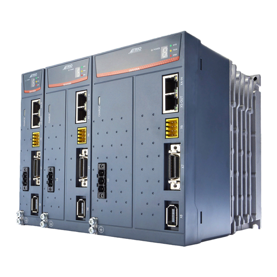
EARTH SCREW
X8 ENCODER CONNECTOR
X7 I/O SIGNAL CONNECTOR
X6 SAFETY CONNECTOR
X5 ETHERCAT OUT
X4 ETHERCAT IN
X3 MOTOR CONNECTOR
HIGH VOLTAGE CHARGE LED
STATUS DISPLAY
QUICK START GUIDE
DX4-1A5A ... DX4-130A
DX4
X1 MAIN CIRCUIT CONNECTOR
X2 CONTROL CIRCUIT CONNECTOR
GROUND TERMINAL
Advertisement

Related Manuals for Estun Trio DX4


Summary of Contents for Estun Trio DX4
- Page 1 EARTH SCREW X8 ENCODER CONNECTOR X7 I/O SIGNAL CONNECTOR X6 SAFETY CONNECTOR X5 ETHERCAT OUT X1 MAIN CIRCUIT CONNECTOR X4 ETHERCAT IN X2 CONTROL CIRCUIT CONNECTOR X3 MOTOR CONNECTOR GROUND TERMINAL HIGH VOLTAGE CHARGE LED STATUS DISPLAY QUICK START GUIDE DX4-1A5A ...
-
Page 2: Safety Warning
SAFETY WARNING During the installation or use of control systems, users of Trio products must ensure that there is no possibility of injury to any person or damage to machinery. Control systems, especially during installation, can malfunction or behave unexpectedly. Bearing this in mind, users must ensure that even in the event of a malfunction or unexpected behaviour, the safety of an operator or programmer is never compromised. - Page 3 POWER SUPPLY CONNECTOR WIRING Prepare the following items before preparing the wiring for the Main Circuit Terminals and Control Circuit Terminals. You will require: Flat-blade with tip width of 3.0mm to 3.5mm screwdriver: Cold pressed Sleeve type ferrule with cross-section from 1.5mm to 2.5mm terminals: and a length of 10mm...
- Page 4 POWER SUPPLY CONNECTORS (X1, X2) Symbols Name Specifications and Reference Control power supply Single-phase, 200V ac to 240V ac, -15% to +10%, L1C, L2C terminals 50Hz or 60Hz There is a factory fit short between B2 and B3. Regenerative Resistor When the busbar capacitance is insufficient, B1, B2, B3 terminal...
- Page 5 RJ45 ETHERNET CONNECTOR (X4 AND X5) EtherCAT communication (X4-IN and X5-OUT) are RJ45 terminals. The communication cable from the network master or controller should be connected to X4-IN and X5-OUT should be connected to the X4-IN terminal of the next Drive (or network device) Signal Description Send data +...
- Page 6 STO FUNCTION SIGNALS (X6) PIN 7 PIN 8 This product has the integrated safety function Safe Torque Off (STO) according to IEC 61800-5-2, which is equivalent to an uncontrolled stop in accordance with stop category 0 of IEC 60204-1, which can protect people from dangerous movements of the machine and reduce the risk to the operator.
- Page 7 I/O CONNECTOR (X7) Name Type Function TP1+ Input PIN 1 PIN 14 Touch Probe Input 1 TP1- Input TP2+ Input Touch Probe Input 2 TP2- Input PIN 13 PIN 26 Power supply to DIN signals, connect to a 24V dc DIN_COM Input power supply or 0V.
- Page 8 ENCODER PORT (X8) Symbols Color PG5V PG0V Black PIN 10 PIN 9 Green Green-Black PIN 2 PIN 1 Blue Blue-Black BAT+ Yellow BAT- Yellow-Black Shell Frame ground ENCODER BATTERY CONNECTION Absolute encoders are fitted on motors with an encoder type of L. These encoders require a battery supply to retain the absolute encoder data when the Drive power is removed.
- Page 9 DISPLAY The Status indicators on the Drive show the status of the EtherCAT network and the servo control. The POWER LED indicates power is present to the Control board. The CHARGE LED indicates the voltage level on the Main circuit. The seven-segment display shows the status of the motor control.
- Page 10 MOUNTING DIMENSIONS (LOOKING FROM FRONT) The Drives are based mounted and should be fitted to a non-painted metal surface. Mount the Drive vertically, as is shown below. Mount the Drives so that the Display Panel is facing toward the operator. Prepare two or three mounting holes for the Drive and mount it securely in the mounting holes (The number of mounting holes depends on the size of the Drive).
- Page 11 INSTALLING DRIVE(S) IN A CONTROL CABINET When installing a drive or drives, use the image below as a reference for free space around the installation. mounting plate ≥50 ≥50 ≥30 ≥30 Mounting allowance between ≥30 ≥30 Wiring mounting plate and cabinet ≥50 ≥50 allowance...
- Page 12 180mm 38-95mm UK | USA | CHINA | INDIA WWW.TRIOMOTION.COM T H E M O T I O N S P E C I A L I S T CAD data Drawings to aid packaging and mounting are available in various formats from the Trio web site. Products should be wired by qualified persons.
Need help?
Do you have a question about the Trio DX4 and is the answer not in the manual?
Questions and answers