SystemAir SAVE VSR 150/B User Manual
Hide thumbs
Also See for SAVE VSR 150/B:
- Installation instructions manual (60 pages) ,
- Installation and service (48 pages) ,
- Service & accessories installation manual (48 pages)
Table of Contents
Advertisement
Quick Links
Advertisement
Table of Contents

Related Manuals for SystemAir SAVE VSR 150/B


Summary of Contents for SystemAir SAVE VSR 150/B
- Page 1 SAVE VSR 150/B User Manual Document in original language | 211457 · A001...
- Page 2 © Copyright Systemair UAB All rights reserved E&OE Systemair UAB reserves the rights to change their products without notice. This also applies to products already ordered, as long as it does not affect the previously agreed specifications. 211457 | A001...
-
Page 3: Table Of Contents
Contents Disposal and recycling ........1 Duct system maintenance ....... 18 Warnings............1 Cleaning extract louvres and supply air diffusers..........18 Type label............2 Checking the outdoor air intake ....19 QR code ..........2 Checking the roof cowl (if fitted)....19 Product description..........2 Checking and cleaning the duct SAVECair control ..........2 system .......... -
Page 5: Disposal And Recycling
Disposal and recycling | Disposal and recycling This product is compliant to the WEEE directive. When disposing the unit, follow your local rules and regulations. This product packing materials are recyclable and can be reused. Do not dispose in household waste. -
Page 6: Type Label
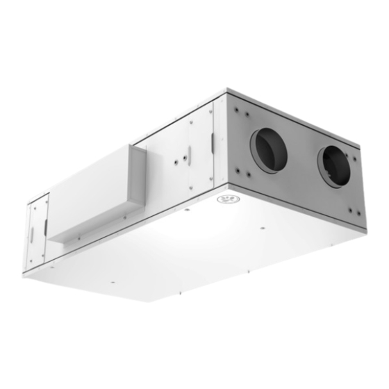
Fig. 2 Example of QR code label Product description The SAVE VSR 150/B is a heat recovery ventilation unit with two built in rotating heat exchangers. The SAVE VSR 150/B is suitable for houses with up to 100 m heated living area. It supplies filtered outdoor air to residential areas and ex- tract air from bathroom, kitchen and wet rooms. -
Page 7: Startup Wizard
SAVECair control | Settings are done by touching the icons or options. The touch screen is sensitive and it is not necessary to press too hard. Startup wizard During the first power up of the unit, you will be asked to set: •... -
Page 8: Menu Overview
| SAVECair control Menu overview A. Return to home screen B. Basic read-only information about the unit C. Currently active alarms and alarm history D. Configure and check week schedule E. Check and change remaining time till filter change F. General system preferences G. -
Page 9: Home Screen
SAVECair control | Home screen Touching home icon (pos. A) in drop- down menu list (pos. 1) will always returns you to home screen after commissioning. 1. Drop-down menu list 2. Active user mode 3. Airflow settings 4. Temperature settings 5. - Page 10 | SAVECair control Icon Text Description Sets speed of both supply and extract air fans to Low levels when user is away from home for a long period of time. HOLIDAY ECO mode is active. Delay in days. Sets speed of both supply and extract air fans to maximum High levels and temperature setpoint offset to –3 K when apartment is more crowded than usual.
-
Page 11: Temperature Settings
SAVECair control | 5.5.2 Temperature settings Temperature can be set at SET TEMPERATURE menu accessible from the home screen by touching TEMPERATURE icon with thermometer. Default temperature value is 18°C (range 12–30°C). Use up and down arrows or a slider to change the value. Then touch the SET to confirm changes. -
Page 12: Indoor Air Quality
| SAVECair control Important It is not recommended to set fan to Off in standard households. If manual fan stop is activated, the unit should be provided with dampers in exhaust and fresh air ducts to avoid cold draught and risk of condensation when the unit has been stopped. -
Page 13: Week Schedule
SAVECair control | Icon Text Description Function prevents formation of the ice on the heat exchanger during cold Defrosting outdoor temperatures. Warm air from the living space is used to defrost the heat exchanger using a damper inside the outdoor air duct. The unit switches from outdoor air to Secondary air secondary air while the extract air fan stops and warm secondary air increases the temperature inside the heat exchanger. -
Page 14: Maintenance Of The Unit
Scheduled time period is displayed in blue colour on the clock (pos. 4). Maintenance of the unit Maintenance of the SAVE VSR 150/B should normally be performed 3 - 4 times a year. Warnings Danger •... -
Page 15: Changing Filters
Maintenance of the unit | Fig. 4 Open the side cover Note: Do not forget to tighten screws back after the maintenance! Changing filters Danger Make sure that the Mains supply to the unit is disconnected before performing any maintenance or electrical work! Note: Depending on how the unit is mounted, the filters are accessed differently. -
Page 16: Filters Accessed Through The Filter Cover Plates
| Maintenance of the unit 2. Open the side cover. See chapter 6.2. 3. Pull out the filters towards you. Some force may be needed. 4. Insert the new filters. Make sure that the correct filter types are inserted. 5. Replace and fasten the side cover and connect the unit to mains. 6. -
Page 17: Cleaning The Fans
Maintenance of the unit | Fig. 6 Heat exchanger Even if the required maintenance is carried out, dust will build up in the exchanger block. It is therefore of vital impor- tance for the upkeep of a high efficiency that the exchanger block is removed from the unit and cleaned periodically as described below. -
Page 18: Replacing Rotor Drive Belt
| Maintenance of the unit In this view, figure 7, the extract air fan (1) is removed by loosening two screws by hand and the supply air fan (2) by loosening four screws using a screwdriver. If the other side cover is opened, the supply air fan is removed by loosening two screws by hand and the extract air fan is removed by loosening four screws using a screwdriver. - Page 19 Fig. 8 Rotor drive belt (1), belt pulley (2) and location of heat exchanger cables (3) SAVE VSR 150/B units are delivered with two welded drive belts (1) — one mounted and one as extra if replacement is required. Spare belt is enclosed in a plastic pocket with manuals.
- Page 20 | Maintenance of the unit 6. Take out the heat exchanger package. 7. Loosen 8 screws at the front and 4 screws at the back and then 2 screws holding heat exchangers in order to remove a side gable. 8. Remove side gable (1). Remove the broken drive belt (2). 9.
-
Page 21: Temporary Drive Belt Repair Solution When The Belt Pulley Can Be Accessed
Maintenance of the unit | 12.Remount the heat exchanger package and secure it with the screws. 13.Reconnect the heat exchanger cables to the motor and sensor. 14.Insert the extract air filter if it was removed. Remount filter bracket and secure it with screws. 15.Close and fasten the side cover and connect the unit to mains. -
Page 22: Overheat Protection Reset Button
| Duct system maintenance 6. Thread the new drive belt around both heat exchangers and the belt pulley. 7. Put the ”empty” end of the drive belt on to the nipple 8. Press the ends completely together to secure a tight joint. 9. -
Page 23: Checking The Outdoor Air Intake
Troubleshooting | Checking the outdoor air intake Leaves and pollution could plug up the air intake grille and reduce the capacity. Check the air intake grille, and clean as necessary. It is recommended to do this at least twice a year. Checking the roof cowl (if fitted) The roof cowl (if fitted) connected to the exhaust air duct needs to be checked at least twice a year and cleaned if necessary. -
Page 24: Alarms
| Alarms Action Malfunction 1. Check the display for alarms. 2. Check the active user functions in HMI screen if Defrosting function is running. 3. Check set supply air temperature in the HMI. 4. Check if ECO mode is activated in HMI (it is a power saving function and prevents the heater from activating). - Page 25 Alarms | Alarm name Explanation Do the following Rotation speed of the supply air fan Check quick connectors of the fan. Supply air fan rpm is lower than minimum required. Fan Contact your installation company or malfunction. place of purchase. •...
- Page 26 | Alarms Alarm name Explanation Do the following Secondary air defrosting failed. Check if secondary air damper is in Secondary air damper Outdoor air temperature sensor correct position. measures < 10°C in 2 sec after Check that damper is connected defrosting properly and cable is not damaged.
- Page 27 Alarms | Alarm name Explanation Do the following External stop Unit is stopped by external signal. Operation is stopped by digital signal from external remote device or signal from building management system. Manual fan stop active Operation stopped, fans are in Select another speed of fans (LOW / manual mode and selected as OFF.
- Page 28 Systemair UAB Linų st. 101 LT–20174 Ukmergė, LITHUANIA Phone +370 340 60165 Fax +370 340 60166 www.systemair.com...
Need help?
Do you have a question about the SAVE VSR 150/B and is the answer not in the manual?
Questions and answers