Table of Contents
Advertisement
Quick Links
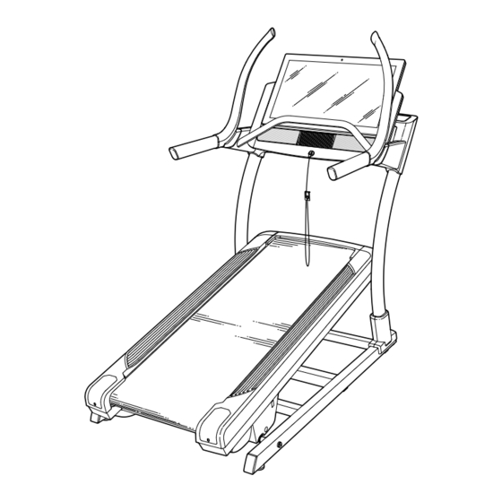
Model No. NTL39221-INT.0
Serial No.
Write the serial number in the space
above for reference.
CUSTOMER SERVICE
UNITED KINGDOM
Call: 0330 123 1045
From Ireland: 053 92 36102
Website: iconsupport.eu
E-mail: csuk@iconeurope.com
Write:
ICON Health & Fitness, Ltd.
Unit 4, Westgate Court
Silkwood Park
OSSETT
WF5 9TT
UNITED KINGDOM
AUSTRALIA
Call: 1800 993 770
E-mail: australiacc@iconfitness.com
Write:
ICON Health & Fitness, Inc.
PO Box 635
WINSTON HILLS NSW 2153
AUSTRALIA
CAUTION
Read all precautions and
instructions in this manual before
using this equipment. Save this
manual for future reference.
Serial
Number
Decal
USER'S MANUAL
iconeurope.com
Advertisement
Table of Contents

Related Manuals for NordicTrack NTL39221-INT.0


Summary of Contents for NordicTrack NTL39221-INT.0
- Page 1 Model No. NTL39221-INT.0 Serial No. USER’S MANUAL Write the serial number in the space above for reference. Serial Number Decal CUSTOMER SERVICE UNITED KINGDOM Call: 0330 123 1045 From Ireland: 053 92 36102 Website: iconsupport.eu E-mail: csuk@iconeurope.com Write: ICON Health & Fitness, Ltd.
-
Page 2: Table Of Contents
Note: The decals may not be shown at actual size. NORDICTRACK and IFIT are registered trademarks of ICON Health & Fitness, Inc. Google Maps is a trademark of Google LLC. The Bluetooth word mark and logos are registered trademarks of Bluetooth SIG, Inc. and are ®... -
Page 3: Important Precautions
IMPORTANT PRECAUTIONS WARNING: To reduce the risk of burns, fire, electric shock, or injury to persons, read all important precautions and instructions in this manual and all warnings on your incline trainer before using your incline trainer. ICON assumes no responsibility for personal injury or property damage sustained by or through the use of this product. - Page 4 20. Keep fingers, hair, and clothing away from 24. Never insert any object into any opening on the moving walking belt. the incline trainer. 21. The incline trainer is capable of high speeds. 25. Inspect and properly tighten all parts each Adjust the speed in small increments to time the incline trainer is used.
-
Page 5: Before You Begin
BEFORE YOU BEGIN Thank you for selecting the revolutionary reading this manual, please see the front cover of this NORDICTRACK COMMERCIAL X32I incline trainer. manual. To help us assist you, note the product model ® The COMMERCIAL X32I incline trainer offers a selec- number and serial number before contacting us. -
Page 6: Part Identification Chart
PART IDENTIFICATION CHART Use the drawings below to identify small parts used for assembly. The number in parentheses below each draw- ing is the key number of the part, from the PART LIST near the end of this manual. The number following the key number is the quantity used for assembly. -
Page 7: Assembly
ASSEMBLY • Assembly requires two persons. • To identify small parts, see page 6. • Place all parts in a cleared area and remove the • Assembly requires the following tools: packing materials. Do not remove the protective plastic sheet on the console until assembly is the included hex keys completed. - Page 8 2. Make sure that the power cord is unplugged. Remove the four 3/8" x 3 1/4" Screws (18) from the Base (74) (only one side is shown). Save the Screws. 3. Remove the four 3/8" x 2 3/4" Screws (22) from the Uprights (83).
- Page 9 4. Set the Uprights (83) on the Base (74). Make sure that the hole with the Upright Wire (75) is on the right side. Attach the right Upright (83) with two of the 3/8" x 3 1/4" Screws (18) and two of the 3/8"...
- Page 10 Set the left handrail assembly (C) on the floor in the position shown. Attach the Push Bar Bottom (109) to the left handrail assembly (C) with two 5/16" x 3/4" Patch Screws (108); do not fully tighten the Patch Screws yet. Attach the Push Bar Bottom (109) to the right handrail assembly (D) in the same way.
- Page 11 8. With the help of a second person, position the handrail assembly (E) below the Console (93) as shown. Then, move both sides of the hand- rail assembly upward at the same time, sliding the inner corner (F) of the handrail assembly between the Console (93) and the Console Base (92).
- Page 12 10. If necessary, move the incline trainer to the desired location (see HOW TO MOVE THE INCLINE TRAINER on page 25). After the incline trainer is placed in the loca- tion where it will be used, make sure that the incline trainer rests firmly on the floor.
-
Page 13: How To Use The Incline Trainer
HOW TO USE THE INCLINE TRAINER HOW TO PLUG IN THE POWER CORD Follow the steps below to plug in the power cord. This product must be earthed. If it should malfunc- 1. Plug the indicated end of the power cord (A) into the tion or break down, earthing provides a path of least socket on the incline trainer (B). - Page 14 CONSOLE DIAGRAM FEATURES OF THE CONSOLE When you use the manual mode, you can change the speed and incline of the incline trainer with the touch The advanced incline trainer console offers a selec- of a button. As you exercise, the console will display tion of features designed to make your workouts more instant exercise feedback.
- Page 15 HOW TO TURN ON THE POWER HOW TO USE THE TOUCH SCREEN IMPORTANT: If the incline trainer has been The console features a tablet with a full-color touch exposed to cold temperatures, allow it to warm to screen. The following information will help you become room temperature before you turn on the power.
- Page 16 HOW TO SET UP THE CONSOLE 5. Calibrate the incline system. Before using the incline trainer for the first time, set up First, touch your name or Hello on the screen. the console. Next, select the settings main menu. Then, select the maintenance section, touch Calibrate Incline, 1.
- Page 17 HOW TO USE THE MANUAL MODE Note: If the walking belt is moving at a high speed and you adjust the incline below 0% or 1. Insert the key into the console. above 15.5%, the speed of the walking belt may automatically decrease.
- Page 18 7. When you are finished exercising, remove the 3. Select a map workout. key from the console. To select a map workout, touch the desired button Step onto the foot rails and press the Stop button on the screen. Note: The featured map workouts on the console or tap on the screen.
- Page 19 HOW TO USE A DRAW YOUR OWN MAP 4. Save your workout. WORKOUT Touch Save New Workout on the screen. If desired, Note: To use a draw your own map workout, the change the title of the workout or add a description, console must be connected to a wireless network (see and then press the >...
- Page 20 HOW TO USE A DISTANCE OR TIME WORKOUT 5. Select a distance or time workout that you have previously added to your schedule on iFit.com. Note: To use a distance or time workout, the console must be connected to a wireless network (see HOW Touch the calendar icon to download a distance or TO CONNECT TO A WIRELESS NETWORK on time workout from your schedule.
- Page 21 HOW TO USE THE SLED PUSH FEATURE HOW TO CHANGE CONSOLE SETTINGS 1. Insert the key into the console. IMPORTANT: Some of the settings and features described may not be enabled. Occasionally, a See HOW TO TURN ON THE POWER on page 15. firmware update may cause your console to function slightly differently.
- Page 22 3. Customize the unit of measurement and other 6. Calibrate the incline system of the incline settings. trainer. Touch Calibrate Incline, and then touch Begin to To customize the unit of measurement, the time zone, or other settings, touch Equipment Settings, calibrate the incline system.
- Page 23 HOW TO CONNECT TO A WIRELESS NETWORK An information box will ask if you want to connect to the wireless network. Touch the Connect button The console is Wi-Fi enabled, allowing you to set up a to connect to the network or touch the Cancel but- wireless network connection.
- Page 24 HOW TO USE THE SOUND SYSTEM THE OPTIONAL HEART RATE MONITOR To play music or audio books through the console Whether your sound system while you exercise, you can connect goal is to a personal audio device to the console with an audio burn fat or to cable, or you can connect wirelessly if your device is strengthen your...
-
Page 25: How To Move The Incline Trainer
HOW TO MOVE THE INCLINE TRAINER Before moving the incline trainer, insert the key Carefully roll the incline trainer on the wheels to the into the console (A), raise the incline to the maxi- desired location, and then lower it to the level position. mum incline level, remove the key, and unplug the CAUTION: To reduce the risk of injury, use extreme power cord. -
Page 26: Maintenance And Troubleshooting
MAINTENANCE AND TROUBLESHOOTING MAINTENANCE SYMPTOM: The power turns off during use Regular maintenance is important for optimal a. Check the power switch (see drawing c at the left). performance and to reduce wear. Inspect and prop- If the switch has tripped, wait for five minutes and erly tighten all parts each time the incline trainer is then press the switch back in. - Page 27 SYMPTOM: The displays of the console do not b. If the console does not boot up properly, or if the function properly console freezes and does not respond, reset the console to the factory default settings. IMPORTANT: Doing this will erase all the a.
- Page 28 SYMPTOM: The incline trainer will not connect to SYMPTOM: The walking belt slows when walked on the wireless network a. If an extension cord is needed, use only a 3-conduc- a. Make sure that the wireless settings on the console tor, 14-gauge (2 mm ) cord that is no longer than are correct (see page 23).
- Page 29 SYMPTOM: The walking belt is not centered SYMPTOM: The walking belt slips when walked on between the foot rails a. First, remove the key and UNPLUG THE POWER a. IMPORTANT: If the walking belt rubs against CORD. Using the hex key, turn both idler roller the foot rails (G), the walking belt may become screws clockwise, 1/4 of a turn.
-
Page 30: Exercise Guidelines
EXERCISE GUIDELINES Aerobic Exercise—If your goal is to strengthen your WARNING: cardiovascular system, you must perform aerobic Before beginning this exercise, which is activity that requires large amounts or any exercise program, consult your physi- of oxygen for prolonged periods of time. For aerobic cian. - Page 31 SUGGESTED STRETCHES The correct form for several basic stretches is shown at the right. Move slowly as you stretch —never bounce. 1. Toe Touch Stretch Stand with your knees bent slightly and slowly bend forward from your hips. Allow your back and shoulders to relax as you reach down toward your toes as far as possible.
- Page 32 NOTES...
-
Page 33: Part List
PART LIST Model No. NTL39221-INT.0 R0421A Key No. Qty. Description Key No. Qty. Description 3/8" x 5 1/2" Screw Cushion #8 x 1/2" Pan Head Tek Screw Base Wire 3/8" Star Washer Rubber Cushion #8 x 3/4" Pan Head Tek Screw Large Pivot Bushing #8 x 3/4"... - Page 34 Key No. Qty. Description Key No. Qty. Description Left Inside Handrail Cover 5/16" x 3/4" Screw Right Outside Handrail Cover 5/16" Star Washer Right Inside Handrail Cover #8 x 2" Screw Reed Switch #8 x 1 1/4" Screw Reed Switch Clip #8 x 5/8"...
-
Page 35: Exploded Drawing
EXPLODED DRAWING A Model No. NTL39221-INT.0 R0421A... - Page 36 EXPLODED DRAWING B Model No. NTL39221-INT.0 R0421A...
- Page 37 EXPLODED DRAWING C Model No. NTL39221-INT.0 R0421A...
- Page 38 EXPLODED DRAWING D Model No. NTL39221-INT.0 R0421A...
- Page 39 EXPLODED DRAWING E Model No. NTL39221-INT.0 R0421A...
-
Page 40: Ordering Replacement Parts
ORDERING REPLACEMENT PARTS To order replacement parts, please see the front cover of this manual. To help us assist you, be prepared to provide the following information when contacting us: • the model number and serial number of the product (see the front cover of this manual) •...
Need help?
Do you have a question about the NTL39221-INT.0 and is the answer not in the manual?
Questions and answers