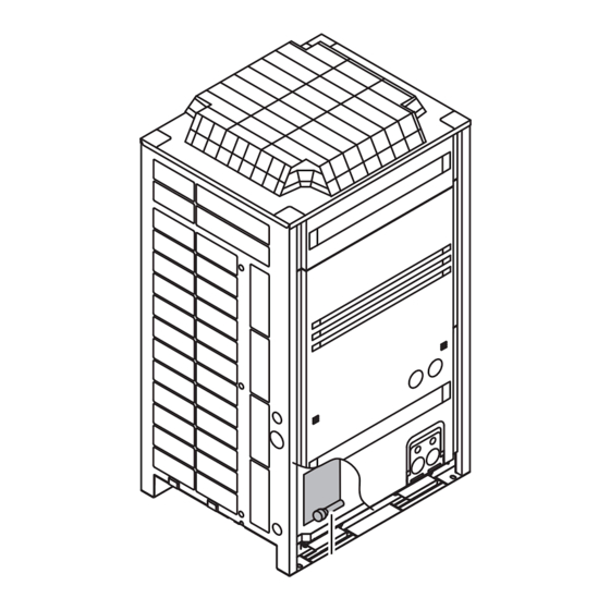
Daikin ERQ200A7W1B Installation Manual

Daikin ERQ200A7W1B Installation Manual

Inverter condensing unit
Hide thumbs Also See for ERQ200A7W1B:

Advertisement

Quick Links

INSTALLATION MANUAL
Inverter condensing unit
ERQ125A7W1B
ERQ200A7W1B
ERQ250A7W1B

Advertisement

Table of Contents
loading

Summary of Contents for Daikin ERQ200A7W1B

  • Page 1 INSTALLATION MANUAL Inverter condensing unit ERQ125A7W1B ERQ200A7W1B ERQ250A7W1B...
  • Page 2 ERQ125 ERQ200+250 A+B+C+D a 10 mm a 50 mm a 200 mm b 300 mm b 100 mm b 300 mm c 10 mm c 50 mm d 500 mm d 500 mm a 10 mm a 50 mm a 200 mm b 300 mm b 100 mm b 300 mm...
  • Page 3: Table Of Contents

    AIKIN ONTENTS Page About L∞p by Daikin ................. 1 L∞p by Daikin is part of Daikin’s wider commitment to reduce our 1. Introduction ................2 environmental footprint. With L∞p by Daikin we want to create a 1.1. Combination ................. 2 circular economy for refrigerants.
  • Page 4: Introduction

    Refer to If not, the unit may fall over and cause damage or the manual "Option kit for combination of Daikin condensing injury. units with field supplied air handling units" for more details.
  • Page 5: Inspecting And Handling The Unit

    NSPECTING AND HANDLING THE UNIT  The equipment described in this manual may cause electronic noise generated from radio-frequency At delivery, the package should be checked and any damage should energy. The equipment complies to specifications that be reported immediately to the carrier claims agent. are designed to provide reasonable protection against When handling the unit, take into account the following: such interference.
  • Page 6: Refrigerant Piping

    Support the unit with a foundation of 67 mm wide or more. (The 6.2. Selection of piping material  support leg of the unit is 67 mm wide, see figure Foreign materials inside pipes (including oils for fabrication)  Fasten the unit in place using four must be 30 mg/10 m or less.
  • Page 7: Connecting The Refrigerant Piping

    6.4. Connecting the refrigerant piping Removing the pinched piping (See figure 9) Front connection or side connection Never remove the pinched piping by brazing. Installation of refrigerant piping is possible as front connection or Any gas or oil remaining inside the stop valve may blow off side connection (when taken out from the bottom) as shown in the pinched piping.
  • Page 8: Protection Against Contamination When Installing Pipes

    Piping length restrictions Precautions when connecting field piping. 4.1 Installation limitations  Perform brazing at the gas stop valve before brazing at the liquid stop valve.  Add brazing material as shown in the figure. Outdoor unit Expansion valve kit Air handling unit ...
  • Page 9: Leak Test And Vacuum Drying

    Vacuum drying: Use a vacuum pump which can evacuate to  EAK TEST AND VACUUM DRYING –100.7 kPa (5 Torr, –755 mm Hg) The units were checked for leaks by the manufacturer. Evacuate the system from the liquid and gas pipes by using a vacuum pump for more than 2 hours and bring the system to After connecting the field piping, perform the following inspections.
  • Page 10: Internal Wiring - Parts Table

    8.1. Internal wiring – Parts table L1,L2,L3 ....Live N......Neutral Refer to the wiring diagram sticker on the unit. The abbreviations .... Field wiring used are listed below: A1P~A7P..... Printed circuit board ....Terminal strip BS1~BS5 .... Push button switch (mode, set, return, test, reset) .......
  • Page 11: Power Circuit And Cable Requirements

    8.3. Power circuit and cable requirements Keep power imbalance within 2% of the supply rating.  • Large imbalance will shorten the life of the smoothing A power circuit (see table below) must be provided for connection of capacitor. the unit. This circuit must be protected with the required safety •...
  • Page 12: System Examples

    8.5. System examples  Use a power wire pipe for the power wiring. (See figure 14)  Outside the unit, make sure the weak low voltage electric wiring (i.e. for the remote control, between Field power supply outdoor unit (400 V) units, etc.) and the high voltage electric wiring do not Fuse pass near each other, keeping them at least 50 mm...
  • Page 13: Field Line Connection: Power Wiring

    Be sure to keep the power line and transmission line When routing ground wires, secure clearance of   apart from each other. 50 mm or more away from compressor lead wires. Failure to observe this instruction properly may  Be careful about polarity of the transmission line.
  • Page 14: Wiring Example For Wiring Inside Unit

    10. C 8.9. Wiring example for wiring inside unit HECKING OF UNIT AND INSTALLATION CONDITIONS figure Electric wiring Be sure to check the following: Wiring between outdoor unit and control box The piping work Clamp to the electric box with field supplied clamps. Make sure piping size is correct.
  • Page 15: Precautions When Adding R410A

    Make sure to tighten the cap securely. Refer to the table below CAUTION Tightening torque N•m (Turn clockwise to close) In Europe, the Greenhouse gas emissions of the total Shaft refrigerant charge in the system (expressed as tonnes CO equivalent) is used to determine the maintenance intervals. Hexagonal Stop valve size Valve body...
  • Page 16: Checks After Adding Refrigerant

    Error code  "11.3. Stop valve operation procedure" on NOTE Close valve A immediately. Check page 13 for details on how to handle stop valves. following items:  The refrigerant charging port is connected to the - Check if the gas side stop valve is opened correctly piping inside the unit.
  • Page 17: Before Operation

    12. B 12.2. Checks before initial start-up EFORE OPERATION Remark that during the first running period of the unit, NOTE required power input may be higher than stated on the 12.1. Service precautions nameplate of the unit. This phenomenon originates from the compressor that needs elapse of a 50 hours run in period before reaching smooth operation and stable power consumption.
  • Page 18 Location of the dip switches, LEDs and buttons Check operation procedure LED H1~8P Turn the power on for the outdoor unit, the control box and air handling unit. Push button switches BS1~BS5 Be sure to turn the power on at least 6 hours before operation Dip switch 1 (DS1: 1~4) inorder to have power running to the crank case heater.
  • Page 19: Test Operation

    Push the button and the setting is defined. BS3 RETURN Setting mode 2 When the button is pushed again, the operation BS3 RETURN starts according to the setting. The H1P LED is on. Refer to the service manual for more details and for other settings. Setting procedure Push the button according to the required function...
  • Page 20: Service Mode Operation

    Check operation procedure Correcting after abnormal completion of the test operation The test operation is only completed if there is no malfunction code Close the electric box lid and all front panels except the one on displayed on the remote controller. In case of a displayed malfunction the side of the electric box.
  • Page 21: Caution For Refrigerant Leaks

    Cut off the power supply to the control box, air handling unit and Calculate the smallest room volume (m the outdoor unit with the circuit breaker. After the power supply In a case such as the following, calculate the volume of (A), (B) to one side is cut off, cut off the power supply to the other side as a single room or as the smallest room.
  • Page 23 TO IN-D F1 F2 P1 P2 F1 F2 L1 L2 TO IN/D UNIT F1 F2 A B C A B C C/H SELECTOR TO IN/D UNIT F1 F2 P1 P2 P1 P2 A B C A B C 15 16...
  • Page 24 4PW51323-1D – 2022.10...

This manual is also suitable for:

Erq125a7w1bErq250a7w1bErq-aw1

Table of Contents