
Related Manuals for Miller Intellifire 204


Summary of Contents for Miller Intellifire 204
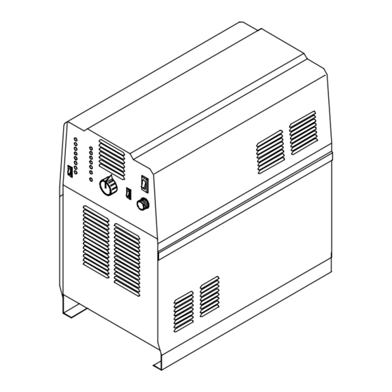
- Page 1 OM-196 202B February 2005 Processes Induction Heating Description Induction Heating Power Source Intellifire 204 Visit our website at www.MillerWelds.com...
- Page 2 We know you don’t have time to do it any other way. That’s why when Niels Miller first started building arc welders in 1929, he made sure his products offered long-lasting value and superior quality.
-
Page 3: Table Of Contents
TABLE OF CONTENTS SECTION 1 − SAFETY PRECAUTIONS − READ BEFORE USING ....... . 1-1. -
Page 5: Section 1 − Safety Precautions − Read Before Using
SECTION 1 − SAFETY PRECAUTIONS − READ BEFORE USING 1-1. Symbol Usage safety_ihom 8/03 Means Warning! Watch Out! There are possible hazards with this procedure! The possible hazards are shown in the adjoining symbols. Y Marks a special safety message. This group of symbols means Warning! Watch Out! possible ELECTRIC SHOCK, MOVING PARTS, and HOT PARTS hazards. -
Page 6: Additional Symbols For Installation, Operation, And Maintenance
1-3. Additional Symbols for Installation, Operation, and Maintenance FALLING UNIT can cause injury. OVERUSE can cause OVERHEATING D Use handle and have person of adequate D Allow cooling period. physical strength lift unit. D Reduce output or reduce duty cycle before D Move unit with hand cart or similar device. -
Page 7: Section 2 − Mesures De Securite Pour Le Chauffage Par Induction
SECTION 2 − MESURES DE SECURITE POUR LE CHAUFFAGE PAR INDUCTION ihom_fre 8/03 AVERTISSEMENT LE CHAUFFAGE PAR INDUCTION peut être dangereux. PRENDRE LES MESURES NECESSAIRES POUR EVITER LES RISQUES DE BLESSURES GRAVES, VOIRE MORTELLES. TENIR LES ENFANTS A DISTANCE. LES PORTEURS D’UN STIMULATEUR CARDIAQUE DOIVENT PREALABLEMENT CONSULTER LEUR MEDECIN. -
Page 8: Dangers Supplémentaires De Mise En Route, De Fonctionnement Et D'entretien
DES FUMEES ET DES GAZ peuvent 5. Travailler dans un espace fermé seulement s’il est bien ventilé ou en portant un respirateur. Demander toujours à un surveillant être dangereux pour votre santé. dûment formé de se tenir à proximité. Des fumées et des gaz Le chauffage à... -
Page 9: Informations Concernant Les Champs Électro-Magnétiques (Information Emf)
2-2. Informations concernant les champs électro-magnétiques (Information EMF) Considérations relatives au chauffage à induction et aux effets des proposer des recommandations scientifiques claires pour des champs électriques et magnétiques basse fréquence. stratégies à suivre en vue de minimiser ou de prévenir des risques potentiels.”... -
Page 10: Section 3 − Installation
SECTION 3 − INSTALLATION 3-1. Specifications Amperes Input at Required Rated Load Output 50 Output Reflective Rated Output or 60 Hz, Three-Phase Overall Dimensions Weight Frequency Frequency Inductance Inductance 400 V Length: 31 in 20 kW At (787 mm) 100% Duty Width: 16 in 160 lb 2.5 To 50 μh... -
Page 11: Remote 14 Receptacle Rc14 Information And Connections
3-3. Remote 14 Receptacle RC14 Information and Connections Front Panel Plug Threaded Collar Keyway Remote 14 Receptacle RC14 (See Section 3-4) To connect to receptacle, align key- way, insert plug, and tighten threaded collar. C L N sb7.1* 3/93 - Ref. S-0004-A / Ref. S-0750 / Ref. ST-801 826-C 3-4. -
Page 12: Connecting Input Power
3-5. Connecting Input Power Tools Needed: 3/8 in 5/16 in Ref. ST-801 825-C Have only qualified persons make this state, and local electrical codes. Route input Install and connect grounding conductor and installation. power cord through strain relief on rear panel input conductors in conduit or equivalent to to fuse block. -
Page 13: Electrical Service Guide
3-6. Electrical Service Guide Input Voltage Input Amperes At Rated Output Max Recommended Standard Fuse Rating In Amperes Time-Delay Normal Operating 3 Min Input Conductor Size In AWG/Kcmil Max Recommended Input Conductor Length In Feet (Meters) (83) Min Grounding Conductor Size In AWG/Kcmil Reference: 1999 National Electrical Code (NEC) 1 Consult factory for circuit breaker applications. -
Page 14: Section 5 − Maintenance & Troubleshooting
SECTION 5 − MAINTENANCE & TROUBLESHOOTING 5-1. Routine Maintenance Y Disconnect power Maintain more often before maintaining. during severe conditions. 3 Months Clean and tighten Repair or replace output connections. cracked cables and cords. 6 Months Replace damaged or Blow out or vacuum unreadable labels. -
Page 15: Measuring Tuning Capacitor Voltage
5-5. Measuring Tuning Capacitor Voltage Y Significant AC voltage can remain on Turn power source capacitors after unit is Off. Always disconnect input power. check ALL capacitors as shown to be Remove wrapper. sure they have discharged before Tuning Capacitor C1 working on unit. -
Page 16: Ground Fault Protection
5-6. Ground Fault Protection Ground fault protection circuitry automatically shuts down the power source output potentially hazardous condition exists at the heating device connected to the power source (e.g. insulation has broken down on a heating blanket causing the conductor to come into contact with the workpiece or a heating coil touches the workpiece causing a short in the output circuit). -
Page 17: Measuring Input Capacitor Voltage
5-7. Measuring Input Capacitor Voltage Turn power source Y Significant DC voltage can remain on disconnect input power. capacitors after unit is Off. Always check ALL capacitors as shown to be Remove wrapper. sure they have discharged before Input Capacitor C2 working on unit. -
Page 18: Diagnostic Led's
5-8. Diagnostic LED’s Diagnostic LED’s Use diagnostic LED’s to determine operating condition power source. Current Source Limit: 110 A Fault: 115 A Over Frequency Limit: 50 kHz Fault: 55 kHz Under Frequency Limit: 10 kHz Fault: 5 kHz Current Reactive Limit: 700 A Tank Voltage Limit: 670 V Fault: 1100 V Peak... -
Page 19: Troubleshooting
5-9. Troubleshooting Trouble Remedy No heat output. Replace building line fuse or reset circuit breaker. Secure head/coil connecting plate to power source connecting block (see Section 3-2). Check and replace Power switch if necessary. Connect power source to proper input voltage or check for low line voltage. No heat output;... -
Page 20: Section 6 − Electrical Diagram
SECTION 6 − ELECTRICAL DIAGRAM Figure 5-1. Circuit Diagram OM-196 202 Page 16... - Page 21 200 161-A OM-196 202 Page 17...
-
Page 22: Section 7 − Parts List
SECTION 7 − PARTS LIST Hardware is common and not available unless listed. 801 828-E Figure 7-1. Main Assembly OM-196 202 Page 18... - Page 23 Item Dia. Part Mkgs. Description Quantity Figure 7-1. Main Assembly ....179 245 PANEL, side LH ..........
- Page 24 Item Dia. Part Mkgs. Description Quantity Figure 7-2. Center Baffle Assembly (Fig 6-1 Item 2) . . . PM1,2 ..223 949 KIT, transistor IGBT module ........
- Page 25 Item Dia. Part Mkgs. Description Quantity Figure 7-2. Center Baffle Assembly (Fig 6-1 Item 2)(Continued) ....179 233 WINDTUNNEL LH ..........
- Page 26 Notes...
- Page 27 Effective January 1, 2005 (Equipment with a serial number preface of “LF” or newer) This limited warranty supersedes all previous Miller warranties and is exclusive with no other Warranty Questions? guarantees or warranties expressed or implied. Call LIMITED WARRANTY − Subject to the terms and conditions Induction Heating Coils and Blankets below, Miller Electric Mfg.
- Page 28 Contact the Delivering Carrier to: File a claim for loss or damage during shipment. For assistance in filing or settling claims, contact your distributor and/or equipment manufacturer’s Transportation Department. © PRINTED IN USA 2005 Miller Electric Mfg. Co. 1/05...
Need help?
Do you have a question about the Intellifire 204 and is the answer not in the manual?
Questions and answers