Advertisement
Quick Links
Instruction Manual
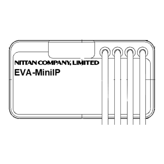
VDOT-Mini IP Mini Input Module
Before Installation
Please read these instructions carefully and keep for future reference.
The information in this document is subject to change without notice.
For updates please refer to our website.
Do not use the products outside the rated power supply voltage range
specified in the Specifications. It may cause a fire or damage to
equipment.
!
Do not disassemble, repair, or modify the products. It may cause a fire or
electric shock.
!
Make sure to turn the power off before commencing any wiring work.
Otherwise it may cause electric shock or damage to equipment.
Note: Follow the requirements for the installation of the product in
accordance with the Specifications. Otherwise it may cause damage to
equipment.
Note: Do not install the product in any location where oil, dust, iron
powder, chemicals, or hydrogen sulphide may occur or affect the product.
It may cause damage to equipment.
This package contains the following items:
Main unit..............................................................................1
Instruction Manual
...............................................................1
EOL Resistor (VDOT-RE-10k)......................................................1
Sealing label...........................................................................1
General Description
VDOT-MiniIP Mini Input Module is intended for use in addressable two
wire systems. The module monitors and transmits the status (normal,
open, short, or active) of devices equipped with NC/NO dry contacts to a
control panel. The initiating device circuit (IDC) can be wired on
Class B.
General Operation
Normal standby condition: The module receives polling from the control
panel at the regular interval.
Active condition: When the external input is activated, the module
communicates to the control panel the active status.
CAUTION
!
CAUTION
CAUTION
72-78 MORFA, ROAD, SWANSEA, SA1 2EN
Trouble condition: The module communicates to the control panel the
open/short status of IDC, depending on the Subtype Setting described
below.
Compatibility Requirement
To ensure proper operation, the module shall be connected to UL listed
control panel series. Any conventional detector cannot be connected
with the module.
Before Installing
Disconnect power to the control panel before installing the module. If
the module is installed in an existing operational system, inform the
operators and local authorities that the system will be temporarily out
of service.
Mounting
Mount or place the module on the back or inside of monitored unit. Its
small size and light weight allow it to be installed without rigid
mounting.
Setting
・Address Setting
Use VDOT-AD2 Programmer for setting the address of the module prior
to installation. VDOT-MiniIP has an address given at random from
factory. Connect the Programmer with the address setting port to
change the address to any of 1-254 (dec), with reference to the
instruction manual of VDOT-AD2 Programmer. The address can be set
regardless of whether power supply from the control panel is turned on
or off. Refer to Figure 1.
1
ZETA ALARMS LIMITED
http://www.velocitydetection.com
ADDRESS SETTING PORT
Figure 1
GLT-299-7-17 Rev.1
Jan 24, 2022
mm(in)
Advertisement

Summary of Contents for Velocity VDOT-Mini IP
- Page 1 Instruction Manual ZETA ALARMS LIMITED 72-78 MORFA, ROAD, SWANSEA, SA1 2EN VDOT-Mini IP Mini Input Module http://www.velocitydetection.com Before Installation Trouble condition: The module communicates to the control panel the Please read these instructions carefully and keep for future reference. open/short status of IDC, depending on the Subtype Setting described The information in this document is subject to change without notice.
- Page 2 Subtype 5 and 6 can be used with the control panel complying with UL864 10 edition. Normally Close Class B Please contact Velocity customer service for any required details. Dry contact switch and EOL (10k ohm) are connected in series between A+ and A- in VDOT-MiniIP. Wiring Dry contact is ON.
- Page 3 Maintenance Specifications Routine inspection: Ensure the module is secure and undamaged. SLC (Signaling Line Circuit) Rated Range 20 to 38VDC Applied Voltage Operation Test SLC Current Consumption Standby 1.7mA The purpose of the Operational Test is to confirm the product’s correct Activated 7.2mA (max) operation.
- Page 4 Warranties 1.1 Zeta warrants to the customers that: (a) all products supplied hereunder will be of merchantable quality and will comply with any specification agreed between Zeta and customer. (b) it is not aware of any rights of any third party in the market which would or might render the sale of the products, or the use of any of the trade marks on or in products, or the use of any of the trade marks on or in relation to the products, unlawful.

Need help?
Do you have a question about the VDOT-Mini IP and is the answer not in the manual?
Questions and answers