
Subscribe to Our Youtube Channel
Related Manuals for MAKSIWA BMS 3200.IR


Summary of Contents for MAKSIWA BMS 3200.IR
- Page 1 BMS 3200.IR Sliding Panel Saw 3200 mm INSTRUCTION MANUAL ATTENTION: FOR YOUR SAFETY, READ INSTRUCTIONS CAREFULLY BEFORE ASSEMBLING OR USING THIS PRODUCT. SAVE THIS MANUAL FOR FUTURE REFERENCE.
- Page 2 Greetings, Congratulations, you just purchased the BMS.3200.IR Precision Saw, which was developed with the Maksiwa’s highest standards of technology and quality. Your BMS.3200.IR Precision Saw allows you to have the highest productivity in woodworking. Besides a great fi nish, the BMS.3200.IR ensures that your cuts are always precise.
- Page 3 Furthermore, the manual must be kept to hand and within the vicinity of the machine so that it is accessible to operators when using, maintaining or repairing the machine. Maksiwa International Inc. 4100 N Powerline Rd, Suite D3 Pompa-...
-
Page 4: Table Of Contents
Contents 1. General..................................05 1.1 Foreword .................................05 1.2 Machine Identifi cation ..........................05 1.3 Customer Service recommendations ......................05 1.4 Copyright ..............................06 1.5 Spare Parts ..............................06 1.6 Disposal .................................06 2. Safety Precautions...............................07 2.1 Safety Regulations ............................07 2.2 Residual Risks ..............................08 2.3 Safety and Information Signals........................09 3. -
Page 5: General
1 General 1 General Information 1.1 Foreword This machine is desinged to make straight and angle cut for wood material, especially for wood board cutting. Some information and illustrations in this manual may difer from the machine in your possession, since all the confi... -
Page 6: Copyright
1 General 1.4 Copyright This manual should be handled confi dentially. It is designated solely for those persons who work on or with the machine. All descriptions, texts, drawings, photos and other depictions are protected by copyright and other commercial laws. Illegal use of the materials is punishable by law. This manual, in its entirety or parts thereof, may not be transferred to third parties or copied in any way or form, and its contents may not be used or otherwise communicated without the express written consent of the manufacturer. -
Page 7: Safety Precautions
2 Safety Regulations 2 Safety Precautions 2.1 Safety Regulations WARNING Indicates imminent risks which may cause serious injury to the operator or other persons. Indicates imminent risks which may cause serious injury to the operator or other persons. Be careful and scrupulously follow the instructions. The manufacturer disclaims all responsibilities for damages to persons or things, which might be caused by any failure to comply with the safety regulations. -
Page 8: Residual Risks
2 Description • Connect the dust suction hoods to an adequate suction system; suction must always be activated when the machine is switched on. • Never open doors or protections when the machine or the system is operating. • Many unpleasant experiences have shown that anybody may wear objects which could cause serious accidents. - Page 9 2.3 Machine Safety This signals may be applied on the machine; in some cases they indicate possible danger conditions, in others they serve as indication. Always take the utmost care. SAFETY SIGNALS: Risk of eye injury. Wear eye protection. Wear hearing protection systems. Danger of electric shock.
-
Page 10: Specifi Cations
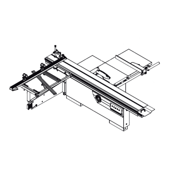
3 Description 3 Specifi cations 3.1 Main Components 3.1 Main Components 1 - Right extension table 5 - Rear extension table 9 - Tilting handwheel 2 - Main table 6 - Sliding table 10 - Rip fance assemnly 3 - Blade guard assembly 7 - Telescopic fence 4 - Blade 8 - Square sliding table... -
Page 11: Electrical Connection
3 Description 3.3 Electrical Connection - Electrical installation should be carried out by competent, qualifi ed personnel. - The mains connection should be made using the terminal box. - Replacement of the power supply cable should only be done by a qualifi ed electrician. - Connect the main leads to a standard 220V±10% (60Hz+1%Hz) electrical supply which has protection devices of under-voltage, over-voltage, over-current the main connection must have maximum 25A time-lag fuse. - Page 12 3 Description...
- Page 13 3 Description...
-
Page 14: Noise Level
3 Description 3.4 Noise Level No Load Load Sound Pressure Level < 80.4cB (A) < 85.7dB (A) Sound Power Level < 98.1dB (A) < 100.7dB (A) Associated uncertainty K=4dB Measurement made in accordance with EN ISO 3746:1995 and EN ISO 11202:1995 The noise levels measured are emission levels and not necessarily the safe working level. -
Page 15: Safety Devices
3 Description Connect the mouths to the suction system with fl exible tubes of adequate diameter. Tighten with clamps. The tube must be positioned in such a way so as not to obstruct the operator during machining. WARNING Indicates imminent risks which may cause serious injury to the operator or other persons. Indicates imminent risks which may cause serious injury to the operator or other persons. -
Page 16: Installation
4 Installation 4 Installation CAUTION Assembly need to be done by an experienced and trained person. 4.1 Contents of Package • The machine is supplied partly assembled. Prior to use, further assembly is required. • When unpacking the machine the following components are included for the initial assembly. •... -
Page 17: Lifting And Unloading
4 Installation 4.2 Lifting and Unloading WARNING Lifting and handing should only be carried out by skilled personel specially trained to execute this kind of Lifting and handing should only be carried out by skilled personel specially trained to execute this kind of operations. -
Page 18: Installation Zone Characteristic
4 Installation 4.3 Installation Zone Characteristics WARNING It is prohibited to install the machine in explosive environments. The installation zone must be selected evaluating the work space required depending on the dimension of the pieces to be machined,and taking into account that a free space of at least 800 mm must be left around the machine.It is also necessary to check the fl... -
Page 19: Install Of Loose Parts - Introduction
4 Installation 4.4 Install of Loose Parts - Introduction A few elements will be disassembled from the machine main structure due to packaging and shipping requirements. These loose parts should be installed as follows. WARNING Please tighten all bolts and nuts absolutely. Otherwise, may cause machine wobble or serious injury to the operator or other persons. - Page 20 4 Installation 4.4.3 RIP FENCE PRECISION ADJUSTMENT • Tools Required for Assembly: 10mm Allen wrench • Pass B, C, and D through E and fix them on A (don't fix them too tightly, there are four sets) • Adjust the slider to the alignment bolt, then tightened the Allen bolts “ Fig.4.4.3 4.4.4 INSTALL SQUARE SLIDING TABLE •...
- Page 21 4 Installation 4.4.6 INSTALL FENCE RAIL Tools Required for Assembly: - Wrench 18mm • L Wrench 16mm • Install scale seat B to tables with screw 1. • Put the scale A into the slot of scale seat B. • Install guide rail C on the workbench through parts 2, 3, 4, and 5 Fig.4.4.6 4.4.7 INSTALL RIP FENCE...
-
Page 22: Adjustment
5 Adjustment 5 Adjustment WARNING Handle the tools with protective gloves. 5.1 Setup and control WARNING WARNING For cutting panels coated with fi nishingmaterial, you have to use the scorer F. Position the scoring saw blade in order to have an engraving equal to 2mm. Proceed as follows if it is necessary to adjust scorer positioning with respect to the saw: Tools Required for Assembly: - L wrench 5mm - Loosen the hand wheel A, then use the handle B to adjust the saw blade height, after that, tighten the hand... -
Page 23: Rip Fence Precision Adjustment
5 Adjustment • Wrench 16mm • Put the straight edge B on the main table and extension tables, use feeler gauge to check the fl atness. • Re-tighten the bolts A to micro-adjust the fl atness. 5.3 Rip Fence Precision Adjustment Tools Required for Assembly: •... - Page 24 5 Adjustment 5.4 M30 Angle Meter Instruction Manual • S5 digital tube display, clear and easy to read • Measuring scope:±180° • Automatically read the angle for unexpected power outage - Buttons can be locked, avoiding faulty operation. • Angle data react quickly •...
- Page 25 5 Adjustment 5.4.3 DISPLAY INSTRUCTION Display content Info. Statement -179.9~180.0 Display the measured angle Display item no. when turning on Err06 Sensor fault:1)sensor damaged:2)sensor wire damaged:3)display function damage Beyond Angle linear correction, calibration failure 5.4.4 MENU INSTRUCTION Function Description Parameter Default Parameter Description Remarks...
- Page 26 5 Adjustment 5.4.5 Fast Adjustment Internal calibration has been done at factory, if customers have need to do further liner calibration, please following below steps (take woodworking equipment as an example): 1. Equipment operate to the initial position, long press the ZERO key, the current Angle will be set to 0 ° 2.
-
Page 27: Operating Procedures
6 Operating Procedures 6 Operating Procedures WARNING WARNING Please be careful to operate the machine while saw blade Please be careful to operate the machine while saw blade is running and always DO NOT to use the machine unless all of the guards and other safety devices are in good working order. -
Page 28: Working With The Machine
6 Operating Procedures 6.3 Working with the Machine The choice of the method to use to make a cut with the circular saw depends on the dimensions of the wood to be machined and the type of machining to be carried out. For cutting ennobled wood, use of the engraver is indispensable to prevent chipping.When the engraver is not needed,lower it completely underneath the table. -
Page 29: Correct Use For This Machine
6 Operating Procedures 6.4 Correct Use for this Machine • First make sure that the machine does not vibrate.Do not try to take off the material when the cut has already started; proceed with a continuous and uniform speed. Workpiece feeding towards the blade (especially where there are knots) should not be too fast (feeding speed should be in accordance with workpiece thickness). -
Page 30: Maintenance
7 Maintenance 7 Maintenance WARNING WARNING Disconnect the general power supply before doing any maintenance. Disconnect the general power supply before doing any maintenance. 7.1 Replace Saw Blade WARNING WARNING Only correctly sharpened saw blades manufactured in accordance with the requirements of EN 847-1:2005 Only correctly sharpened saw blades manufactured in accordance with the requirements of EN 847-1:2005 shall be used. -
Page 31: General Lubrication
7 Maintenance In particular, clean the following parts: - the sliding table rail A; - the sliding support extension B; 7.3 General Lubrication • Weekly clean and lubricate all the mobile couplings of the machine A with a thin fi lm of oil and grease. •... -
Page 32: Trouble Shooting
8 Trouble Shooting 8 Trouble Shooting WARNING WARNING - For any information or problem contact your area dealer or our technical service center. The necessary interventions must be carried out by specialised technical personel. - Before carrying out any fault service or maintenance work, please always TRUN OFF THE SWITCH, UNPLUG POWER CABLE, WAIT FOR SAW BLADE TO COME TO STANDSTILL. -
Page 33: Exploded View
9 Exploded View 9 Exploded View Frame Assembly - SHEET A... - Page 34 9 Exploded View Frame Assembly - SHEET A Item Parts Name Part No Item Parts Name Part No SCREW M10 M10X25GB7 SCREW M5 M5X70GB70D1B Nut M10 M10GB6170Z REAR PLATE JXPS1201010002C SCREW M8 M8X20GBGB80B SCREW M6 M6X20GB70D1Z FRAME JXPS1205011000G SCREW M12 M12X100GB77B BOLT M10 M10X50GB5781Z...
- Page 35 9 Exploded View Spindle Assembly - SHEET B...
- Page 36 9 Exploded View Spindle Assembly - SHEET B Item Parts Name Part No Item Parts Name Part No MAIN SHAFT JXPS1201021005B WASHER 6 WSH6GB97D1Z BEARING BRG6005- SCREW M6X20 M6X10GB70D1Z 2RSHGB276SKF LIMIT PLATE JXPS1205091007 SLEEVE JXPS1201021007 SCREW 12 M12X50GB77B MAIN SHAFT SEAT JXPS1205021001 SCREW DUST COVER JXPS1205020005...
- Page 37 9 Exploded View With knife plate Assembly - SHEET C Item Parts Name Part No Qty. SCREW M10 M10X55GB70D3Z SCREW M8 M8×30GB77B RIVING KNIFE LOCKING PLATE JXPS1201028008A RIVING KNIFE ADJUSTING PLATE JXPS1205028007 RIVING KNIFE JXPS1201028001A RIVING KNIFE LOCKING BLOCK JXPS1201028005 RIVING KNIFE SEAT JXPS1205028002 SCREW M8...
- Page 38 9 Exploded View Motor Assembly - SHEET D Item Parts Name Part No Qty. Item Parts Name Part No Qty. ADJUSTING NUT JXPS1205023005 MOTOR SEAT ASSY JXPS1205023002A SCREW JXPS1201023006B 1 PH MOTOR YLA903302A TENSION BLOCK JXPS1201023004B 3 PH MOTOR YSA105402 FLAT WASHER 16 WSH16GB97D1Z Bolt M10...
- Page 39 9 Exploded View Pre-Cut motor Assembly - SHEET E Item Parts Name Part No Qty. Item Parts Name Part No Qty. GAS SPRING SUPPORT SHAFT JXPS1205024008 SCREW M6X16 M6X16GB70D3Z NUT M6 M6GB61706170Z SUPPORTING SHAFT JXPS1205024005 GAS SPRING JXPS1201020013B SCORING MOTOR WHEEL JXPS1201024001E NUT M6X20 M6X20GB70D1Z...
- Page 40 9 Exploded View Pre-cutting adjustment Assembly - SHEET F Item Parts Name Part No Qty. NUT M10 M10GB6172D1Z SCORING ADJUSTING SEAT JXPS1205027002 FLAT WASHER 10 WSH10GB97D1Z BUSHING JXPS1201027001A LOCK HANDLE ASSY JXPS1201027100 LOACK WHEEL JXTS1201028004 SCREW M8X25 M8X25GB70D1Z SPRING WASHER 8 WSH8GB93Z...
- Page 41 9 Exploded View Pre-Cut shaft seat Assembly - SHEET G Item Parts Name Part No Qty. Item Parts Name Part No Qty. NUT M16 M18GB6173Z SNAP RING CLP42GB893D1B SCORING SAW BLADE CLIP JXPS1201022002 SPACER JXBS1603010003 SLOTTED SAW BLADE JXPS1201022003 SCREW M6X12 M6X12GB70D2Z SCORING MAIN SHAFT JXPS1201022004C...
- Page 42 9 Exploded View Main saw lift Assembly - SHEET H...
- Page 43 9 Exploded View Main saw lift Assembly - SHEET H Item Parts Name Part No Item Parts Name Part No HANDLE GEAR JXPS1602026402 HAND WHEEL JXPS1205025100 FLAT KEY PLN5X5X20GB1096 SET SCREW M5X6GB77B BRACKET JXPS1205025001 SCREW M6X16GB70D1Z SHAFT SLEEVE P17X15X15GB12613 FLAT KEY PLN6X6X25GB1096 WASHER BRG1730AX-...
- Page 44 9 Exploded View Rotational support seat Assembly - SHEET I Item Parts Name Part No Qty. BOLT M10X30 M10X30GB5783Z SPRING WASHER 10 WSH10GB93Z WASHER 10 WSH10GB97D1Z TAPER PIN 8X30 PIN8X30GB118Z ROTARY SUPPORT SEAT JXPS1201020002E...
- Page 45 9 Exploded View Core Assembly - SHEET J...
- Page 46 9 Exploded View Core Assembly - SHEET J Item Parts Name Part No Item Parts Name Part No WASHER 5 WSH5GB97D1Z DUST HOSE FDPS1201020009 SCREW M5X12 M5X12GB70D2Z SCREW M6X16 M6X16GB70D2Z DUST GUARD JXPS1201020103 SCREW M4X35 M4X35GB818Z LOCKNUT M5 M5GB889D1Z SAFETY SWITCH QKS7 RACK JXPS1205020001...
- Page 47 9 Exploded View Defl ection worm Assembly - SHEET K Item Parts Name Part No Qty. Item Parts Name Part No Qty. ROUND NUT 0000301849F SINK HOLE WASHER JXPS1201026012 COVER WSH20GB87D1Z SCREW M6 M6X30GB70D3Z AXIAL NEEDLE AND CAGE ASSY BRG2035AXKASGB4605 HANDWHEEL COVER JXPS1205026202 WRAPPED BUSHES...
- Page 48 9 Exploded View Table Assembly - SHEET L...
- Page 49 9 Exploded View Table Assembly - SHEET L Item Parts Name Part No QTY. Item Parts Name Part No QTY. BOLT M10x25GB5783Z LOCK HANDLE ROD JXPS1201061014C FLAT WASHER WSH10GB96Z MICRO ADJUSTMENT JXPS1201061010- HANDLE 001S MAIN TABLE JXPS1205030001 RING CLP19GB893D1B SCREW M5x16GB70Z TUBE JXPS1201061015...
- Page 50 9 Exploded View Sliding Table Assembly - SHEET M Item Parts Name Part No Qty. Item Parts Name Part No Qty. RUBBER FEET JXSM0401042108 PLATE JXSM0401042001 PLATE JXSM0401042107-001S SLIDE BRACKET JXSM0401042002 JXSM0401042106 SLIDE TABLE JXPS1201041000F JXSM0401042101 HANDLE JXPS1201040002 SHAFT JXSM0401042103 HEX SLIDER JXPS1201040001 SPRING...
- Page 51 9 Exploded View SquareSlidingTableAssembly - SHEET N Item Parts Name Part No Qty. Item Parts Name Part No Qty. ROLLER JXPS1604051002 END CAP GRPS1401051003 END CAP JXPS1201051014 LOCK BLOCK JXPS120105106 THIN NUT M10 M10GB6172D1Z GUIDE BLOCK JXPS1201051015A SCREW M10 M10X45GB70D1Z SCREW M6X20GB70Z SCREW M6...
- Page 52 9 Exploded View SupportBracketAssembly - SHEET O Item Parts Name Part No Qty. Item Parts Name Part No Qty. SCREW M6X20GB70D2Z SCREW SCPS1601052015 COVER JXPS1602052005 BEARING ROLLING WHEEL SCPS1601052007 CREW M5X10GB818Z ECCENTRIC SHAFT SCPS1601052004 HEX NUT M6GB6170Z BEARING ROLLING WHEEL SCPS1601052019 SUPPORT BRACKET JXPS1602052003B...
- Page 53 9 Exploded View TelescopicFenceAssembly - SHEET P Item Parts Name Part No Qty. Item Parts Name Part No Qty. SCREW M5X4GB80B WASHER WSH8GB96Z LOCK SLIDER JXPS1201053009 SCALE BRACKET JXPS1201053120 SCALE JXPS1201053006C TUBE JXPS1201053118 SCALE JXPS1201053006D DOUBLE-END BOLT M10X70GB/T889B END CAP JXPS1201053105A LOCK BUTTON JXPS1201053111...
- Page 54 9 Exploded View Adjustable Angle guid-e -SHEET Q Item Parts Name Part No Qty. Item Parts Name Part No Qty. SCREW M6X30GB14Z HANDLE BALL 0804011-01 ANGLE DIAL JXPS1205054004 WASHER WSH6GB96D1Z LOCKING HANDLE JL82060008 SCREW M6X20GB70D3Z RIVET RVT2D5X5GB827C T-BAR JXPS1205054002 LEFT BAFFLE PLUG JL20062008 SCREW M6X40GB70D3Z...
- Page 55 9 Exploded View Fixed blade cover Assembly - SHEET R...
- Page 56 9 Exploded View Fixed blade cover Assembly - SHEET R Item Parts Name Part No QTY. Item Parts Name Part No QTY. LOCK PLATE JXPS1602080004 COPPER BUSH JXPS1201083006 SPRING WASHE WSH6GB93Z SCREW JXPS1201083001 SCREW M6 M6X12GB70D2Z CONNECTING SOLDERING JXPS1602081400 PLATE NUT CAP JXPS1201083005 LOCK NUT...
-
Page 57: Terms Of Warranty
10 Terms of Warranty 10 Terms of Warranty MAKSIWA assures the owner that their equipment, identifi ed by the Serial number issued on the Warranty Terms. The equipment under warranty, for two (2) years, is as followed: 1. The warranty period begins on the date of the Warranty Terms below. - Page 58 Imported by: Maksiwa International Inc. 4100 N Powerline Rd, Suite D3 Pompano Beach, Florida ZIP Code: 33073 Telephone: +1 (754) 205-6717 | Call us free: +1 (844) 319-6594 E-mail: tech@maksiwa.com www.maksiwa.com...
Need help?
Do you have a question about the BMS 3200.IR and is the answer not in the manual?
Questions and answers