
Subscribe to Our Youtube Channel
Related Manuals for MAKSIWA BMS.3200.IR


Summary of Contents for MAKSIWA BMS.3200.IR
- Page 1 BMS.3200.IR S. C. Sliding Panel Saw 3200 mm INSTRUCTION MANUAL Attention: Read this manual before using the machine.
- Page 2 Maksiwa’s highest standards of technology and quality. Your BMS.3200.IR Precision Saw allows you to have the highest productivity in woodworking. Besides a great finish, the BMS.3200.IR ensures that your cuts are always precise. It should be noted that to use this machine with maximum efficiency, you should read and understand the instructions in this manual.
-
Page 3: Table Of Contents
Index 1 Safey Regulations................................05 1.1 Workspace...................................05 1.2 Electrical Safety................................05 1.3 Personal Safety.................................06 1.4 Machine Safety................................06 2 Description..................................09 2.1 Specifications................................09 2.2 Components................................10 2.2.1 Mobile Arm................................11 2.2.2 Mobile Table Guide.............................11 2.2.3 Blade Tilt Control Handle..........................12 2.2.4 Control Panel..............................13 2.2.5 Emergency Buttons/Switches........................14 2.2.6 Main Table Lock..............................15 2.2.7 Sliding Table Handle............................15 2.2.8 Adjustable Table Handle..........................16 2.2.9 Adjustable Angle Guide..........................17... - Page 4 4.1.2 Scoring Blade Adjustments..........................43 4.1.3 How to Cut at Different Angles........................45 4.1.4 How to Setup for Recurrent Cuts.........................46 4.1.5 Running a Piece..............................47 4.1.6 Cross Cutting..............................48 4.1.7 Cutting Frames, Boxes and Other Four-Sided Pieces..............48 4.1.8 Bevel Cuts................................49 4.1.9 Support for Long Parts..........................49 5 Maintenance..................................50 5.1 General Cleanliness..............................50 5.2 Electrical Maintenance............................50...
-
Page 5: Safey Regulations
If this Machine does not operate properly, first check the power supply. • The BMS.3200.IR is constructed with two separate layers of electrical insulation. You do not have to ground the machine if the power supply comes built with an ground. -
Page 6: Personal Safety
1 Safety Regulations 1.3 Personal Safety • Stay alert, pay attention at what you are doing and use common sense when operating the machine. Do not use the machine when you are tired or under the influence of drugs, alcohol, or medication. - Page 7 1 Safety Regulations performance. A blade cover or any other part that is damaged must be repaired or replaced immediately. Do not use the machine if any the switches do not work properly. • Never leave the machine running unattended. Turn off the main power switch when not in use to prevent any accidents.
- Page 8 1 Safety Regulations guide when making a cross-section cut; and never cut a large workpiece with loose knots or other defects. • ATTENTION: Any powder created by sanding, cutting, grinding, drilling, and other activities contains chemicals that can cause cancer, birth and other reproductive harm. Some examples of these products are: in lead;...
-
Page 9: Description
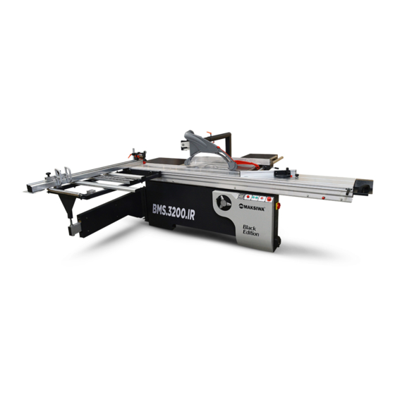
The BMS.3200.IR Black Edition precision saw is designed to provide excellent finishing cuts of MDF sheets. It has a slope of axis from 0º to 45º with digital display. Reinforced structure the BMS.3200.IR Black Edition supports panels with a thickness of 25 mm (1 in). It also has a scoring blade to provide quality cuts. -
Page 10: Components
2 Description 2.2 Components Mobile Arm 16. Wood Panel Clamp 2. Mobile Table Guide 17. Aluminum Table Guide 3. Blade Tilt Control Handle 18. Scoring Blade Adjustment Handles 4. Control Panel 19. Wood Panel Stopper 5. Emergency Buttons/Switches 20. Blade Height Adjustment Handle 6. -
Page 11: Mobile Arm
2 Description 2.2.1 Mobile Arm Enables greater cutting range and greater ergonomics for the operator. 2.2.2 Mobile Table Guide It is used to support larger workpieces and make cross cuts. Can be placed throughout the movable table. -
Page 12: Blade Tilt Control Handle
2 Description 2.2.3 Blade Tilt Control Handle It is used to tilt both saw blades manually. The slope of the saw ranges from 0 to 45 degrees. -
Page 13: Control Panel
2 Description 2.2.4 Control Panel At the control panel you control all the functions and cutting devices of the machine. Digital panel: Shows the angle of the saw blades. 2. POWER button: When the STOP button is released, the POWER button lights up. The machine will be energized. -
Page 14: Emergency Buttons/Switches
2 Description 2.2.5 Emergency Buttons/Switches The emergency switches are used to power the machine and turn it off. Main Power Switch: Powers the machine and the machine control panel. -
Page 15: Main Table Lock
2 Description 2.2.6 Main Table Lock When applied it locks the movable table structure, when released it unlocks the movable table. 2.2.7 Sliding Table Handle It is used to push the movable table during the cut. Ensures greater operator ergonomics. -
Page 16: Adjustable Table Handle
2 Description 2.2.8 Adjustable Table Handle It is used to push the movable table during the cut and It can be moved through the table. -
Page 17: Adjustable Angle Guide
2 Description 2.2.9 Adjustable Angle Guide It is used to make cross cuts from 0 to 45 degrees. 2.2.10 Rear Extension Table Provides an increase to the work area. It holds a ruler. -
Page 18: Rear Extension Table Guide
2 Description 2.2.11 Rear Extension Table Guide It is intended to be used as a reference to cut multiple pieces at the same measurement. Guide ruler: It is fixed throughout the table. 2. Guide frame: Made of cast iron. 3. Aluminum guide: It is fixed to the guide frame and serves as a support for the workpiece. -
Page 19: Panel Pushing Handle
2 Description 2.2.12 Panel Pushing Handle It is used to push the workpiece providing safety for the operator. 2.2.13 Blade Protector Cover It has the function of protecting the operator against splinters and saw dust from cuts. -
Page 20: Dust Collection Port
2 Description 2.2.14 Dust Collection Port Its function is to collect residues and saw dust from cuts. The two outputs have a diameter of 100 mm (3 in). Outlet for upper dust collector: It is located in the saw protection cover. 2. -
Page 21: Support Table
2 Description 2.2.15 Support Table Made of cast iron, it supports internal parts of MDF. 2.2.16 Wood Panel Clamp It is used to lock work pieces on the movable table. -
Page 22: Aluminum Table Guide
2 Description 2.2.17 Aluminum Table Guide Made of aluminum, the movable table guide has the function of adjusting the workpiece in the position the operator wishes and It has a ruler. -
Page 23: Scoring Blade Adjustment Handles
2 Description 2.2.18 Scoring Blade Adjustment Handles They have the function of regulating the scoring blade. Left handle: Raises and lowers the scoring blade. 2. Right handle: Adjust the alignment of the scoring blade in and out. -
Page 24: Wood Panel Stopper
2 Description 2.2.19 Wood Panel Stopper It is located on the aluminum guide of the movable table. It has the function of locking the workpiece in the position desired by the operator. Contains 2 units. Workpiece lock: When lowered, it locks the position of the workpiece. 2. -
Page 25: Blade Height Adjustment Handle
2 Description 2.2.20 Blade Height Adjustment Handle It is used to raise and lower, both the main saw and the scoring blade. 2.2.21 Aluminium Guide Extensions It has the function of extending the work area. -
Page 26: Installation
• Connect the machine’s power wires to an electrical outlet: 380 V, 220 V, 110 V this varies depending on the model of the BMS.3200.IR. • We recommend the installation of circuit breaker be according to the model you have purchased. - Page 27 3 Installation Electrical: Single phase models: 1 phase model 220 V: Main motor: • 17 Amps • 5 HP • Non-loaded blade speed: 4,000 RPM Scoring motor: • 3/4 HP • 2.5 Amps • Non-loaded scoring blade speed: 8,000 RPM 1 phase model 110 V: Main motor: •...
-
Page 28: Assembly
3 Installation 3.2 Assembly • For packaging reasons, the machine is not completely assembled. • If you notice any damage caused by shipping, while opening the package, notify your supplier immediately. Do not operate the machine. • Estimated assembly time: 6 to 7 hours. Carefully removing the machine from the carte, loose components are in the interior of the machine. - Page 29 3 Installation 2. Remove all the Allen bolts from the Support table. After that, install the cylindrical bar of the fixed table. Fig. 1, 2 and 3: Removing the bolts from the Support table. Fig. 4: Bolts removed.
- Page 30 3 Installation 3. Install the fixed table guide cylindrical bar. Fig. 1: Bar positioned. Fig. 2 and 3: Remove the nuts from the base. Fig. 4, 5 and 6: Position the bar on the fixed table and tighten the nuts.
- Page 31 3 Installation 4. Install the Support table extensions. Fig. 1, 2 and 3: Position the rear extension on the Support table. Fig. 4, 5 and 6: Fasten the bolts and tighten them. Fig. 7, 8, 9 and 10: Do the same procedure for extension of the front guide. Fig.
- Page 32 3 Installation 5. Install the saw guard frame on the support table. Fig. 1 and 2: Position the frame on the support table. Fig. 3, 4, 5 and 6: Tighten all bolts.
- Page 33 3 Installation 6. Install the Support table ruler. Fig. 1 and 2: Position the ruler guide on the support table. Fig. 3, 4 and 5: Tighten the bolts. Fig. 6: Installed guide.
- Page 34 3 Installation Install the fixed table guide. Fig. 1, 2, 3 and 4: Position the guide on the support table. Fig. 5 and 6: Fit the aluminum tab into the guide frame.
- Page 35 3 Installation 8. Install the movable table into the fixed table frame. Fig. 1: Place the movable table on top of the fixed table structure, always aligning the holes with the screws. Fig. 2, 3, 4, 5 and 6: Tighten all screws.
- Page 36 3 Installation 9. Install the saw guard into the frame. Fig. 1: Attach the saw guard to the frame. Fig. 2 and 3: Tighten the bolt in the socket. Fig. 4: Installed protector.
- Page 37 3 Installation 10. Install the movable table guide. Fig. 1: Fit the movable table guide and tighten the handles. Fig. 2 and 3: Place the adjustment bracket on the movable guide and tighten the handle. Fig. 4, 5 and 6: Fit the sheet support guide on the movable guide.
- Page 38 3 Installation 11. Install the aluminum tab on the movable table guide. Fig. 1 and 2: Attach the aluminum tab to the movable table guide. Fig. 3, 4, 5 and 6: Tighten all handles.
- Page 39 3 Installation 12. Wood Panel Stopper. Fig. 1 and 2: Fit the wood panel stopper on the aluminum tab and tighten the handles. 13. Install the saw blades. Fig. 1 and 2: Remove the nut. Fig. 3: Fit the saw. Fig.
- Page 40 3 Installation 14. Ready! Your BMS.3200.IR Precision saw is properly installed.
-
Page 41: Operation
Never place your hands close to the cutting area. Put your hands in position no closer than 6 inches from the blade. Hold the piece firmly against the table and the guide during cutting. 4.1 Cutting Setup In the next session you will see how to make cuts with BMS.3200.IR. -
Page 42: Main Blade Adjustments
4 Operation 4.1.1 Main Blade Adjustments Lift the cutting blades by turning the handle counterclockwise. The saw has to be approximately 20 mm (3/4 in) from the height of the sheet to be cut. WOOD Fig. 1: Saw blade raise handle. Fig. -
Page 43: Scoring Blade Adjustments
4 Operation 4.1.2 Scoring Blade Adjustments The function of the scoring system is to perform a surface cut, such as a “scratch” on the workpiece before the main blade cuts. This allows the cut to come out clean, with no chips on the workpiece. It is an optional system;... - Page 44 4 Operation After that, align the scoring blade with the main blade. Turn the right knob clockwise the scoring blade moves to the Right, rotating counterclockwise moves the scoring blade Left. Fig. 1: Handle that move scoring blade left or right. Fig.
-
Page 45: How To Cut At Different Angles
4.1.3 How to Cut at Different Angles The BMS.3200.IR can cut up to 45 degrees. To do this, turn the handle located on the front of the machine to the desired angle and check the angle on the digital display. -
Page 46: How To Setup For Recurrent Cuts
4 Operation 4.1.4 How to Setup for Recurrent Cuts Choose the measurement of the workpiece that you want to cut. Lock the fixed table guide. Then push the piece against the table guide, If the operator wishes, he can secure the workpiece using the wood panel clamp. Fig. -
Page 47: Running A Piece
Turn on the saw and unlock the table, slowly push it until the workpiece meets the saw blades. Fig. 1: Unlocking of the movable table. Fig. 2: BMS.3200.IR cuts entire MDF sheets. Fig. 3. Straight cut. Fig. 4: Cutting at 45 degrees. -
Page 48: Cross Cutting
4 Operation 4.1.6 Cross Cutting • Multi-piece cutting is not recommended, but can be done safely by making sure that each workpiece is securely attached to the table or the guide. A cross-section is made cutting the wood in the opposite direction to the fibers at any angle. A straight cross-section is done with the blade at 0º. -
Page 49: Bevel Cuts
4.1.9 Support for Long Parts • Turn off and unplug the saw. ALWAYS SUPPORT FRAGAILE PIECES. Support long pieces using any convenient supports such as trestles or similar structures to prevent damage. • SEE THE MAKSIWA CATALOG AND FIND PRODUCTS FOR THIS FUNCTION. -
Page 50: Maintenance
5 Maintenance 5 Maintenance Make sure that your machine is disconnected from the power source before performing any maintenance, cleaning, lubrication, adjustments or changing accessories, blades, etc. 5.1 General Cleanliness • Please DO NOT attempt to remove the wood chips while the saw is turned on. •... -
Page 51: Saw Blade Lubrication Chart
5 Maintenance 5.4 Saw Blade Lubrication Chart Machine Model BMS.3200.IR Height Threaded Tilt Where to apply? Sliding table track adjustment Handle base system guide MOBILGREASE HP 222 MOBIL MOBILUX EP2 MOBILGREASE MP ESSO LITHTAN EP2 BEACON 2 SHELL EPRO ALVANIA R2... -
Page 52: Troubleshooting Guide
• For any problem, information or abnormality with the machine, contact the distributor in your area or directly with our service center after sale of MAKSIWA INTERNATIONAL INC., through 844-319-6594 Problem... -
Page 53: Terms Of Warranty
7 Terms of Warranty 7 Terms of Warranty MAKSIWA assures the owner that their equipment, identified by the Serial number issued on the Warranty Terms. The equipment under warranty, for two (2) years, is as followed: The warranty period begins on the date of the Warranty Terms below. - Page 54 Removable of safety equipment will void your warranty. (Riving Blade, Blade Cover, etc.). For your safety, trust the repairs, maintenance and adjustments (including inspection and replacement) for technical assistance recommended by MAKSIWA, always use genuine spare parts and accessories, reassembling to its original machine the same way.
Need help?
Do you have a question about the BMS.3200.IR and is the answer not in the manual?
Questions and answers