
Subscribe to Our Youtube Channel
Related Manuals for QRP Labs QMX


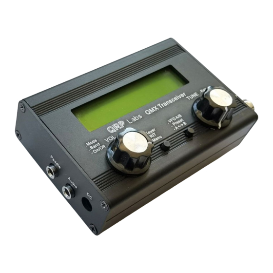
Summary of Contents for QRP Labs QMX
- Page 1 QMX: QRP Labs Multimode Xcvr (transceiver) Assembly manual --- PCB Rev 1 --- QMX assembly Rev 1.00e...
-
Page 2: Table Of Contents
2.26 Install 11mm nylon hex spacer..........................53 2.27 Fit Controls PCB to main PCB..........................54 2.28 Plug together the boards...........................54 2.29 Optional enclosure............................56 2.30 QMX GPS interface and PTT output........................59 2.31 FINAL CHECKS BEFORE APPLYING POWER THE FIRST TIME!................61 2.32 Connections for basic operation........................62 2.33 Firmware installation............................63 3. -
Page 3: Introduction
The operating manual is a separate document and will get you started with QMX with CW, or with your WSJT-X or other digi modes software, in minutes. - Page 4 QMX can be built for 9V or 12V operation! You need to decide NOW! A 9V QMX produces 5 W power output from a supply voltage of 9V or a little over. At 12V, a QMX built for 9V could be producing 8 W power output which is likely to cause over-heating and perhaps failure of the BS170 final transistors.
-
Page 5: Assembly
In the event of a mistake, it is always best to detect and correct any errors as early as possible (immediately after soldering the incorrect component). Again, a reminder: removing a component and re-installing it later is often very difficult! This is particularly true on this QMX design where the components must be installed very close together. - Page 6 Blind via: has one end on the board surface layers, and drills through to an internal layer where it terminates. It does not have a drill hole all the way through the board, so other components and traces could be placed on the opposite board surface or on internal layers without conflict. QMX assembly Rev 1.00e...
- Page 7 For this reason, no blind or buried vias are used in the QMX. It is necessary to use a 6-layer board, but the design is not so complex or compact that blind or buried vias are needed.
- Page 8 QMX assembly Rev 1.00e...
-
Page 9: Pcb Diagrams (Trace, Component Identification)
13. Install all connectors square and well-seated on the boards, to ensure when the boards are plugged together and installed in the enclosure, everything fits properly. 14. Don’t forget: QMX is supplied without firmware. Therefore at first power-up, you must install the latest firmware, a very simple procedure which is described in section 2.32. - Page 10 QMX assembly Rev 1.00e...
- Page 11 QMX assembly Rev 1.00e...
- Page 12 QMX assembly Rev 1.00e...
- Page 13 Trace layout: Top side components: Bottom side components: LCD and controls board are on the following page; there are no SMD components on the bottom side of these boards. QMX assembly Rev 1.00e...
- Page 14 QMX assembly Rev 1.00e...
- Page 15 QMX assembly Rev 1.00e...
- Page 16 QMX assembly Rev 1.00e...
-
Page 17: Parts List
R411, R412, R507 100-ohms SMD 0603 R413, R414 470-ohms SMD 0603 R416 R417 R420 R421 5.1k SMD 0603 R504, R506 1.91k SMD 0603 R509 33-ohms SMD 0603 R514, R516 49.9-ohms SMD 0603 R520, R522 TRIM3339P Trimmer R305 QMX assembly Rev 1.00e... - Page 18 SMD: 78M05 TO252 IC101 SMD: 24M01 SOIC-8 IC201 SMD: SN74AHC1G00DBV IC202 SMD: STM32F446VET6 IC203 SMD: MS5351M IC204 SMD: CS4334 SOIC-8 IC401 SMD: 74CBT3253 SOIC-16 IC402, IC403 SMD: NE5532 SOIC-8 IC404 SMD: LM4562 IC405, IC406 SMD: PCM1804 IC407 QMX assembly Rev 1.00e...
- Page 19 Pin header connector socket (female) Pin header connector socket (female) Pin header connector 17mm long plug (male) Pin header connector plug (male) Pin header connector plug (male) Main PCB, 92 x 139.4 mm 1602 LCD 80x36mm HD44780 LCD module yellow/green QMX assembly Rev 1.00e...
- Page 20 Push-button switch 15mm Knob 365 cm (80-20m version) 0.33 mm diameter wire (AWG #28) (varies depending on QMX version as noted) 65 cm (80-20m version) 0.60 mm diameter wire (AWG #22) (varies depending on QMX version as noted) M3 12 mm...
- Page 21 Frequency dependent parts: 80 / 60 / 40 / 30 / 20m version of QMX: Capacitors (50V, Multi-layer Ceramic capacitors): Value Description Component numbers 22pF Label “220” C403 30pF Label “300” C401 56pF Label “56J” C521, C404 82pF Label “820”...
- Page 22 Inventory parts Note: Photo shows parts for 80/60/40/30/20m version of the QMX. Note: Capacitor colours vary depending on availability. All are NP0/C0G Class-I RF dielectric. QMX assembly Rev 1.00e...
-
Page 23: Install All The Ceramic Capacitors
C522 1200pF Through-hole, label “122” C517 820pF Through-hole, label “821” C518, 514 180pF Through-hole, label “181” C525 22pF Through-hole, label “220” or “22J” C403 220pF Through-hole, label “221” C402 30pF Through-hole, label “300” or “30J” C401 QMX assembly Rev 1.00e... -
Page 24: Install 1N4007 Diodes
D509 & D510, the white stripe is in the right hole; for D512 & D513 the white stripe is in the top hole. Bend one lead over 180-degrees so that the diode body stands up vertically at 90-degrees to the PCB. QMX assembly Rev 1.00e... -
Page 25: Install 47Uh Inductors
The orientation of these is not particularly important, but my recommendation is to follow the silkscreen PCB pattern, putting the body (longer lead) nearer to the PCB lower edge (as orientated in the diagram below) and the wire (shorter lead) nearer to the top side. QMX assembly Rev 1.00e... -
Page 26: Install Bs170 Pa Transistors
Install the BS170 transistors in the positions shown, with their flat faces flush against the PCB. Use the 12mm M3 bolt, washer and nut to firmly press the transistor faces against the PCB, as shown. Refer to the diagram and photographs below. QMX assembly Rev 1.00e... -
Page 27: Assemble And Install Transformer T501
Step 3: Now pass the wire through the top hole of the binocular core, back from left to right. This is the next half-turn of the primary winding, bringing the number of turns so far to 1.5; now we must make the center tap. QMX assembly Rev 1.00e... - Page 28 Cut the wire leaving about 1cm spare. Remember to wind only 2 turns secondary, if winding the transformer as 3:2 for 12V operation. Please refer to page 4 for details of 9V or 12V operation choices. QMX assembly Rev 1.00e...
- Page 29 Do this for the 4 winding ends first, leave the two center-tap for later, to make it easier. Step 13: Cut each of the four wire-endings, leaving about 2mm or less, sticking up from the PCB. QMX assembly Rev 1.00e...
- Page 30 My cheap DMM hasn’t got a continuity mode and I’m using the 2000-ohm resistance mode; in this mode when there is continuity, the reading on mine shows 001 (not zero- ohms; this is just a DMM thing, of no significance). QMX assembly Rev 1.00e...
- Page 31 If any of these tests fail, then you have a soldering problem somewhere, or the wrong wire in the wrong hole, or some short-circuit somewhere etc. This is the final appearance of T501 when the installation is complete: QMX assembly Rev 1.00e...
-
Page 32: Prepare And Install Tapped Inductor L401
1 turn. Step 2: Wind 19 turns then make a loop between the 19 and 20 turns. This is for the 19 turn tap. QMX assembly Rev 1.00e... - Page 33 10 seconds. The enamel burns away in this time. An alternative method is to scrape the wire. QMX assembly Rev 1.00e...
- Page 34 If you do not, then there is a mistake somewhere, most probably a failure to burn away the enamel at one or more of the L401 connections to make a good joint. Here’s the story so far, including the nicely installed L401 tapped inductor. QMX assembly Rev 1.00e...
-
Page 35: Wind And Install L502
For all the toroidal inductors in the QMX kit, you will get it right, if you start as shown (photo, above right) and pass the wire through the toroid from the top side down through the hole, out and then around and over again;... -
Page 36: Install Low Pass Filter Toroids
T30-6 (YELLOW) 2.40uH 37cm L506 T30-6 (YELLOW) 2.88uH 40cm 60 / 40m L512 T30-6 (YELLOW) 1.06uH 26cm 60 / 40m L508 T30-6 (YELLOW) 1.20uH 27cm 30m/20m L513 T30-6 (YELLOW) 393nH 18cm 30m/20m L510 T30-6 (YELLOW) 525nH 20cm QMX assembly Rev 1.00e... -
Page 37: Wind And Install Trifilar Toroid T401
The end result is something like the photo (right). The measurement scale is in cm. Now cut off the untidy ends, and this is the piece of wire that will be used to wind the FT37-43 toroidal core as a trifilar transformer. QMX assembly Rev 1.00e... - Page 38 2mm length then the toroid is more likely to fall out before you’ve had a chance to solder any of the wires. If that happens, it will be tough to get all the wires back in the correct holes again. QMX assembly Rev 1.00e...
- Page 39 A, B, C and pin 7 of IC402 are all connected together. They are also connected to pins 7 and 9 of IC403 which is the 74CBT3253 on the top side of the board. QMX assembly Rev 1.00e...
-
Page 40: Wind And Install Transformer T507
It should protrude about 1mm below the bottom surface of the PCB. You can adjust the 10-turn windings, pushing them around the core such that they are on the top side of the PCB, to achieve this. BEFORE soldering. QMX assembly Rev 1.00e... -
Page 41: Install Connectors
Be very careful to avoid any solder bridges short-circuiting the pins of the connector, which are very close-spaced. QMX assembly Rev 1.00e... -
Page 42: Install Pin Header Connector Sockets (Female)
2x4-pin header connector socket (female) • 2x2-pin header connector socket (female) • Be careful to ensure that the pin headers are accurately aligned, they should sit square in the PCB not at a slightly twisted angle. QMX assembly Rev 1.00e... -
Page 43: Install Power Supply Boards
“spacer” nuts with the removed threads, on the top side of the PCB. Note that the following photographs show incorrect metal screws, not the specified 10mm nylon M3 screws; this is because I had no stock of the nylon screws at the time of the photograph. QMX assembly Rev 1.00e... - Page 44 4. 2x4-pin and 3-pin header connections: Find the 2x4-pin male 90-degree pin header and 2x3-pin. Find the matching female connector sockets (2x4-pin and 2x3-pin). Mate them with their male pin header plugs. QMX assembly Rev 1.00e...
- Page 45 90-degree male headers (2x4-pin and 2x3-pin) to the main board. Again: do not try to force them to sit flush on the surface of the main QMX PCB. Have them suspended off the surface 1mm or whatever, such that the power supply boards sit level.
- Page 46 Be careful while tightening the nuts, not to damage any nearby components such as the SMD components on the power supply boards. Do not over-tighten in your enthusiasm (it’s only nylon). The main QMX board assembly is now complete! QMX assembly Rev 1.00e...
-
Page 47: Install Lcd Module
Solder the component off-cut wires to the top of Turn over the PCB. Ensure the LCD sits flat on the PCB and trim (cut) the excess wire. the PCB before soldering; trim excess. QMX assembly Rev 1.00e... -
Page 48: Install 2X5-Pin And 2X2-Pin Male Pin Header Connectors
Ensure the hex spacers are positioned such that a flat side is parallel to the nearby PCB edge, so that no corners overhang the edge of the PCB, which would prevent the enclosure end panels fitting. QMX assembly Rev 1.00e... -
Page 49: Install 20K Trimmer Potentiometer R47
This potentiometer has four little feet, one in each corner. Unfortunately these make the trimmer too high and it may prevent the PCB from sliding into the QMX-mini enclosure later. Therefore it is necessary to cut off the protruding feet using a wire cutter, so that the potentiometer can sit flat on the PCB. -
Page 50: Install 2X4-Pin Male Header On Controls Pcb
(that will already be installed on the main plastic former of the 2x4-pin header as shown, QMX PCB, in reality, but is shown separately to slide it down the long pins until it sits flush on here for clarity). -
Page 51: Install Rotary Encoders
PCB holes. The printed) side of the PCB. rotary encoder has a locating tab which fits into Do not use the washer. a matching hole on the PCB. Tighten the nut. QMX assembly Rev 1.00e... -
Page 52: Install Tactile Switch Buttons
2.25 Install electret microphone The QMX kit contains an electret microphone which will facilitate future SSB mode support. Install and solder the supplied 6mm electret microphone on the controls PCB. The pins need to be spread apart slightly and it will not sit completely flush on the PCB. -
Page 53: Install 11Mm Nylon Hex Spacer
Push the screw through the hole from the front side of the PCB. Thread the small square spacer PCB that was broken out from the Display PCB panel, onto the screw. Then screw on the 11mm nylon spacer. This completes the Controls PCB assembly. QMX assembly Rev 1.00e... -
Page 54: Fit Controls Pcb To Main Pcb
Controls PCB, as shown in the following photograph. 2.28 Plug together the boards There is a mechanical conflict between the black metal LCD module assembly retaining tab nearest to the 2x5-pin header, and one of the 330uH inductors on the power supply boards. QMX assembly Rev 1.00e... - Page 55 Controls PCB will fit perfectly (though snugly) through the gap in the Display board, and it will be elevated 1.6mm (one PCB’s thickness) above the Display board. QMX assembly Rev 1.00e...
-
Page 56: Optional Enclosure
2.29 Optional enclosure Installation in the QMX enclosure is simple and requires no wiring. It is important to do the assembly in the correct sequence, as follows (Photographs are from the similar QCX-mini). Start with the Display board… … and the main board, with the controls board bolted in position. - Page 57 Make sure you have screws in the panel corners. The screws need the correct way. to be carefully aligned and should screw in easily (if properly aligned). QMX assembly Rev 1.00e...
- Page 58 The grub screw of the volume control knob should be at the position of the flat (hopefully) on the shaft. The grub screw position on the rotary encoder is not important. Disassembly of the QMX should follow similar steps, in reverse. QMX assembly Rev 1.00e...
-
Page 59: Qmx Gps Interface And Ptt Output
QRP Labs QLG2 is perfect for this see http://qrp-labs.com/ql g2 QMX cannot supply +5V for the GPS unit; you need to provide that separately. The GPS signals (PPS and RxD) use the same microcontroller pins as the paddle Dah and Dit respectively. - Page 60 It should be noted that: The QRP Labs 50W PA may not be used in high duty cycle modes such as FT8, JS8 etc at • full power. It should be de-rated to half power operation at maximum, by using a 12V or 13.8V supply.
-
Page 61: Final Checks Before Applying Power The First Time
(long press) to switch on the unit (see next section). 9. When you apply power to your QMX fo rthe first time, it is a very good idea to use a lower supply voltage than you intend to run at, perhaps 7V for example; and use a current-limited supply if possible, perhaps limited to say 250mA. -
Page 62: Connections For Basic Operation
(antenna, and matching unit if applicable). 4) Straight key or paddle To operate the QMX transceiver a straight key or paddle should be connected to the appropriate jack, having a 3.5mm stereo jack plug. The shield (or main body) is ground. It does not really matter which way around the tip and ring connections are (to dit or dah of the paddle) since if they are the wrong way, there is a menu configuration item to swap them around. -
Page 63: Firmware Installation
QMX provides four possible ways to enter firmware update mode: 1. The first time you power up your QMX, there is no firmware on the QMX. It will automatically enter firmware update mode and stay in firmware update mode until you have successfully installed the firmware. - Page 64 2. EEPROM contents: the QMX configuration and log file (if enabled). Again, you can read the file from QMX or write a new one to QMX, simply by dragging files in your file manager application.
- Page 65 Or copy and paste it, however you wish. The file on the QRP Labs website is a ZIPPED file, please be sure to unzip it to get the .QMX file before copying it to QMX.
-
Page 66: Resources
If for any reason, the firmware update did not execute correctly, you cannot access either the user interface on the QMX or log in via the terminal, and you need to force the unit to re-enter firmware update mode – you can do this by connecting a wire jumper from the Aux 2 pin to Ground (see diagram below) then re-starting QMX (cycle the power supply voltage).
Need help?
Do you have a question about the QMX and is the answer not in the manual?
Questions and answers