Advertisement
Quick Links
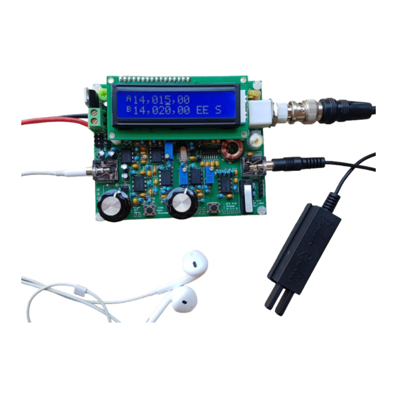
Page 1 of 25
QCX Troubleshooting
I have fixed several QCX kits. The following describes my fault-finding procedure. You can follow these steps too.
Even if your QCX radio works perfectly, signal tracing through the circuit as described on this page, is a very educational
experience! You will find you get a greater and deeper understanding of how the QCX works and why. Even *I* find it
highly rewarding, and I'm the guy who designed the thing! So - get inside your QCX! Be at one with the circuit! Live the
QCX!
Contents
Circuit blocks
Equipment
General checks before starting
Techniques for replacing components
Signal tracing with an oscilloscope
Digital section
LCD all black blocks, or all blank
LCD top row is blocks, bottom row is blank
Unreliable processor boot up
Wrong band selected
Buttons / rotary encoder don't work properly
RECEIVE signal path
Failure to get BPF peak, or a high enough signal strength reading
I-Q and Phase balance fail to how a minimum
Signal generation by the Si5351A
Signal generator injection into the front end
Low Pass Filter fault
T1 transformer
Quadrature Sampling Detector (QSD), IC4
Audio pre-amp, IC5
IC6 and IC7 phase shift circuits
Signal-tracing through the rest of the audio chain
Examples of receiver section faults I have found
TRANSMIT signal path
Current consumption
IC3 the quad NAND gate
Power Amplifier
Low power output
Conclusion
Circuit blocks
The circuit breaks down into three main blocks, for trouble-shooting purposes: Digital section, Receive signal chain, and
transmit signal chain. I handle them one by one. Often you only have a problem in one of these blocks. Throughout the
trouble-shooting, you need to keep referring to the circuit diagram, AND the component placement diagram.
This diagram shows the digital section (processor, LCD, buttons, rotary encoder, Si5351A Synthesiser) in the green
square at bottom right; the red line shows the transmit signal path, and the blue line shows the receive signal path.
Generally speaking, the receive and transmit paths can be debugged by following the signal through from the start to
finish of the signal path. Sooner or later we will find something wrong. An incorrect signal, or an absent signal, etc. This
will tell us where the fault lies. This is a very methodical approach to the fault-finding and it always works.
Advertisement

Subscribe to Our Youtube Channel
Related Manuals for QRP Labs QCX


Summary of Contents for QRP Labs QCX
- Page 1 You will find you get a greater and deeper understanding of how the QCX works and why. Even *I* find it highly rewarding, and I'm the guy who designed the thing! So - get inside your QCX! Be at one with the circuit! Live the...
- Page 2 You can still use a DVM for some measurements (or the internal DVM of the QCX itself, provided you have the digital section working properly). You do not need anything else - the QCX has its own built- in Signal Generator.
- Page 3 Page 3 of 25 Also don't panic if you had additional components left over: some capacitors are not used in some band versions of the kit. And sometimes the kit packers make a mistake and put in one too many of a component (which is better than one too few, right?).
-
Page 4: Digital Section
The easiest way in this case is to just apply solder above and below the PCB to connect the wire of the component to the respective pads. It does NOT happen often, because on the QCX, most of the traces are on the lower side of the PCB. - Page 5 Page 5 of 25 ...then most commonly, the problem is simply that the LCD contrast trimmer R47 has not been adjusted. This is a very sensitive adjustment (though easier to adjust from PCB Rev 3 onwards). Do not be tempted to assume that the voltage on the contrast pin of the LCD should match the one shown in the manual - it will vary from LCD to LCD.
-
Page 6: Receive Signal Path
On the Rev 3 PCB, this modification is already included as standard, so this paragraph doesn't apply. Whenever I am fault-finding a QCX, if it is a Rev 1 or 2 PCB, I always implement this modification first, before anything else. - Page 7 This is what it looks like on my oscilloscope, at IC3 pin 8. Note the horizontal speed 50ns/div, and the signal frequency measurement on the 'scope, 10.120MHz - this was on a 30m QCX kit. Don't worry too much that is is not a precise- looking square wave.
- Page 8 Page 8 of 25 If you do NOT see a nice 5V peak-peak squarewave here on IC3 pin 8, then you have to trace back further to see why you do not have a signal from the Si5351A Synthesiser chip (IC1). Check on pin 10 of IC3. You should see a 3.3V peak- peak squarewave.
- Page 9 Page 9 of 25 In order to be able to trace an actual signal through the first few stages of the receiver, I first bypass R43 by temporarily soldering a 330-ohm resistor in parallel. This is easy to do on the bottom side of the PCB. Be careful to find R43, at the correct place on the PCB, using the layout diagram - it is right next to the BNC connector.
- Page 10 Page 10 of 25 and the PCB. So no current can flow. This is easy to check, using a DVM to check for DC continuity through the inductors. The same thing applies equally to L4, and the windings of T1. T1 transformer The transformer T1 has multiple functions.
- Page 11 Page 11 of 25 Now we can check at the top end of the long winding of the T1 transformer. Since this long winding and the trimmer capacitor act as a band pass filter, you can see that we see a nice sinewave now. This is labelled "1" in the diagrams above.
- Page 12 Page 12 of 25 Next we can check at the outputs of the secondary windings of T1. These are the windings which feed pin 7 and pin 9 of the Quadrature Sampling Detector (QSD), IC4. Now although the amplitude is a bit weaker now we can still observe it quite well, even after the BPF adds some loss, and after the phase-splitter formed by these two transformer windings and loaded by the Quadrature Sampling Detector's sampling capacitors C43-C46.
- Page 13 Page 13 of 25 Note the difference in amplitude, which is not very important, this is a Double-Balanced QSD, and everything cancels itself out, all sins disappear, and even if they didn't, we still have an amplitude balance adjustment later, which is R27, the I-Q balance trimmer potentiometer.
- Page 14 Page 14 of 25 Quadrature Sampling Detector (QSD), IC4 Next we can actually observe the audio frequency signals, with 700Hz frequency, at the four outputs of the Quadrature Sampling Detector circuit around IC4. Note that from now on, I have changed the horizontal speed to 1ms/division, for suitable observation of 700Hz audio frequency signals.
- Page 15 Page 15 of 25 You should check the waveform on each of R5, R6, R8, R9, which is equivalent to saying, across each of the capacitors C43-C46. You are expecting to see 700Hz audio frequency signals. Yes they all have a slightly different amplitude, but you want them to be approximately equal;...
- Page 16 Page 16 of 25 Audio pre-amp, IC5 Now we will check the audio pre-amp, IC5. The following trace shows IC5 pin 1 (upper trace, Ch 1) and IC5 pin 7 (upper trace, Ch 2). These are the famous "I" and "Q" channels. Notice that I have changed the vertical scale to 5V/division. The waveforms are horrendously distorted.
- Page 17 Page 17 of 25 Now if I shift the Channel 2 trace ("Q" channel) to overlay the Channel 1 trace ("I" channel) you can very clearly see the 90-degree phase offset between the I and Q channels. The amplitude is also very similar.
- Page 18 Page 18 of 25 Now, if you see signals that are wildly different from this, or not with the right phase offset, or not approximately equal amplitude - then worry about IC5 and its surrounding circuits. This is the area of the circuit to examine carefully for faults, dry joints, incorrect component values, solder bridges, etc.
- Page 19 Page 19 of 25 PROBLEM, I am just mentioning it because if you saw the sinewave at IC7A pin 1 looking 3x as big as the one at IC6A pin 1, then this is normal IF you have the swapped resistors. No panic. This screenshot below shows the signals at IC7a pin 1, and IC6a pin 1.
- Page 20 Page 20 of 25 Signal-tracing through the rest of the audio chain I didn't take any more screenshots of the process. You get the idea, hopefully. Just keep going, from left to right across the circuit diagram, checking the output of each op-amp - which is either pin 1 or pin 7 of the dual-op-amp chips IC5, 6, 7, 8, 9 and 10.
-
Page 21: Transmit Signal Path
Page 21 of 25 Examples of receiver section faults I have found 1) There was no signal at R9. But there was a signal across the relevant Quadrature Sampling Detector capacitor C45. I took a closer look visually, at the components nearby. It was easy to see that the wire of resistor R9 was broken (it looked as though it had been cut!). - Page 22 Page 22 of 25 With the radio in ordinary RECEIVE mode, you can check the voltages at all the pins of IC3. I know, you cannot even REACH IC3 because the LCD is in the way. You can temporarily un-plug the LCD while the radio is in receive mode. As long as you don't press any buttons you can be sure that the radio will continue working, even without the LCD.
- Page 23 Page 23 of 25 EXAMPLE: I had one QCX radio for repair, where the current consumption, in receive, was 260mA. IC3 felt very warm to touch. I measured the voltages at the pins, in receive mode... and I saw some strange voltages e.g. 1.4V which were not near to 0V or 5V.
- Page 24 Page 24 of 25 trace in this 'scope screenshot. The lower trace shows the signal at the BS170 gates (the old 5V peak-peak squarewave from IC3 pin 3). Again please ignore "ringing", and unpleasant notches on the trace (explanation: 'scope probes, long ground clip wires, 'scope limited bandwidth, you name it, let's not debate it right now).
- Page 25 If you are using the internal RF power meter facility in the QCX, then remember that this too is not very precise. It is a reasonable indication, for debugging purposes, but it is not a precision instrument.
Need help?
Do you have a question about the QCX and is the answer not in the manual?
Questions and answers