
Related Manuals for Digital Equipment 1200 Series


Summary of Contents for Digital Equipment 1200 Series
- Page 1 DIGITAL Server 1200 Series Service Maintenance Manual Part Number: ER-H2BWW-SM. A01 Digital Equipment Corporation...
- Page 2 The information in this document is subject to change without notice and should not be construed as a commitment by Digital Equipment Corporation. Digital Equipment Corporation assumes no responsibility for any errors that might appear in this document. The software, if any, described in this document is furnished under a license and may be used or copied only in accordance with the terms of such license.
- Page 3 FCC ID: H2XWW1 The FCC wants you to know... This equipment has been tested and found to comply with the limits for a Class B digital device, pursuant to Part 15 of the FCC rules. These limits are designed to provide reasonable protection against harmful interference in a residential installation.
- Page 4 This equipment is in the 2nd Class category (information equipment to be used in a residential area or an adjacent area thereto) and conforms to the standards set by the Voluntary Control Council For Interference by Data Processing Equipment and Electronic Office Machines aimed at preventing radio interference in such residential area.
-
Page 5: Table Of Contents
Contents Preface ......................Product Description System Introduction..................Reliability/Availability................. Server Expansion ..................Server Management and Security............. Server Configurations..................Server Naming Guidelines ................ Product Model Numbering Convention ............Related Material ....................Latest Product Information and Updates ............Entry Server Product Information.............. Updates....................Server Software and Utilities Introduction ..................... - Page 6 Contents Changing the Boot Sequence ................2-10 Speeding up the Boot Process................. 2-11 BIOS Upgrade Utility ..................2-12 SCSI Select Utility .................... 2-13 Diagnostics ..................... 2-14 BIOS Setup Utility Features Introduction ..................... Main ......................Advanced ....................Security Options ..................3-10 Boot ......................
- Page 7 Contents FRU Replacement Introduction ..................... Server Left Side View ..................Server Left-Side View (continued)..............Miscellaneous ....................Labels and Nameplates ................... Service Procedures ..................Recommended Tools ..................BIOS Version Information ................Disconnecting External Devices and Power ............. Removing and Installing the Side Panel ............Server Front View....................
- Page 8 Contents Device Mapping Introduction ..................... Processor Memory Address Map .............. I/O Address Map ..................Server Interrupt Levels ................PCI Configuration Space Address Map ............. IRQ Assignment IRQ Assignment Procedure ................Service Notes ....................
- Page 9 Contents Figures Typical DIGITAL Server 1200 .................. viii 2-1. Typical BIOS Setup Utility Screen................4-1. DIGITAL Server Component Information..............5-1. Server Left Side View (1 of 2) .................. 5-2. Server Left-Side View (2 of 2) .................. 5-3. Unlocking and Removing the Side Panel ..............5-10 5-4.
-
Page 10: Preface
Preface This Service Maintenance Manual is a troubleshooting guide that can be used for reference when servicing DIGITAL Servers. DIGITAL reserves the right to make changes to this Service Maintenance Manual without notice. Accordingly, the illustrations and procedures in this document might not apply to all DIGITAL Servers to be serviced since many of the diagnostic tests are designed to test more than one product. -
Page 11: Typical Digital Server 1200
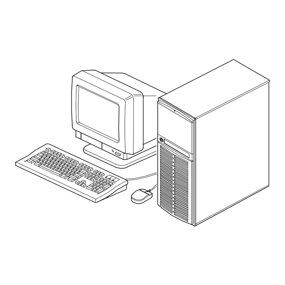
Preface Typical DIGITAL Server 1200 viii... -
Page 12: Product Description
Product Description System Introduction The DIGITAL Server 1200 is a high-performance, highly-scaleable entry level network server featuring the latest in modular processor and storage technology. The DIGITAL Server provides support for the following features: Reliability/Availability Pentium II Processor Module Pentium II processor module. Each Pentium II processor operates using 168-pin, 72-bit DIMMs, 60 ns access time EDO memory, ECC protected. -
Page 13: Server Expansion
Product Description Server Expansion Flexible Memory EDO/ECC memory supported. For Pentium II processor Architecture modules, you can upgrade to a maximum of 512 MB using DIMM memory. Two ISA Expansion Accommodates industry-standard expansion boards such Slots, Four PCI as network, Small Computer System Interface (SCSI), and Expansion Slots, and modems. -
Page 14: Server Management And Security
Product Description Server Management and Security Server Diagnostics Allows local and remote diagnosis of server problems. Hardware Configuration Allows local and remote server configuration. Unique Asset Unique server identifier in non-volatile memory provides Management easy asset management. Firmware Upgrade Utility Upgrades the firmware versions. -
Page 15: Product Model Numbering Convention
Product Description Product Model Numbering Convention The following example describes the product model numbering convention: DIGITAL SERVER 1234 5678A R 1 = PRODUCT FAMILY NAME (first character of family number) 2 = MAJOR PROCESSOR TECHNOLOGY DIFFERENTIATOR WITHIN THE FAMILY This number will be assigned to each new platform based on the following matrix. Open numbers will be assigned as new processor technology is introduced. - Page 16 Product Description 5 = CPU TYPE BLANK = PENTIUM 1= PENTIUM PRO 2 = PENTIUM II/SLOT 1 3 = PENTIUM II/SLOT 2 4 = Open/Available for future processors 5 = Open/Available for future processors 6 = ALPHA EV56 7 = ALPHA PCA57 8 = ALPHA EV6 9 = ALPHA EV67 6, 7, 8,9 = CPU CLOCK SPEED IN MHZ...
-
Page 17: Related Material
Product Description Related Material The following related material is available: Document or Software Title Order Number Description Service Quick Reference ER-H2BWW-SR (English only) Provides troubleshooting information that can be used when servicing DIGITAL servers. Installation Guide ER-H2BWW-IM (Multilanguage)* Provides information on connecting hardware cables and booting the ER-H2BWW-IJ (Japanese) server. - Page 18 Product Description Document or Software Title Order Number Description DIGITAL ServerWORKS software QB-4WY9A-SA Contains ServerWORKS Quick (Multilanguage)* Launch and ServerWORKS Manager software and documentation. Quick Launch consists of a bootable CD-ROM disc and Getting Started guide. This program steps the user through the initial server setup and operating system installation.
-
Page 19: Latest Product Information And Updates
Product Description Latest Product Information and Updates Listed below is the current product information and update source locations. Entry Server Product Information Family Name Model Name Part Number Description DIGITAL Server 1000 DIGITAL Server 1200 2233 FR-H2B3W-AX 6233/512 KERNAL DIGITAL Server 1000 DIGITAL Server 1200 2233 FR-H2B3W-XA 6233/512 MODEL 1... -
Page 20: Server Software And Utilities
Server Software and Utilities Introduction This chapter describes the utilities supplied with the server. Server utilities include: • ServerWORKS Quick Launch This software is used to install a network operating system onto the server. The CD-ROM also contains various drivers and on-line documentation. •... -
Page 21: Serverworks Quick Launch
Server Software and Utilities ServerWORKS Quick Launch ServerWORKS Quick Launch is used to install the server’s Network Operating System (NOS). In addition to providing quick and seamless NOS installation, Quick Launch also provides drivers, documentation, and the ability to make diskettes of utilities such as diagnostics. -
Page 22: Bios Setup Utility
Server Software and Utilities BIOS Setup Utility The BIOS Setup utility enables you to select and store permanently information about the server’s hardware and software in the battery-backed memory of the CMOS RAM. This information takes effect each time the server boots and can be changed any time you run setup. -
Page 23: Accessing The Bios Setup Utility
Server Software and Utilities Use the BIOS Setup utility to: • Change time and date • Enable and disable diskette drives A and B • Select the video system • Select a monitor type • Select cache and shadow features •... -
Page 24: Helpful Hints
Server Software and Utilities Helpful Hints When using the BIOS Setup utility: • Several keyboard keys are assigned to help you select menus and sub- menus, options, change option values, and display help information. These keys are displayed at the bottom of all menus as follows: Function Help (provides a general help screen) Exit (Exits the Setup utility and exits sub menus within the Setup utility) -
Page 25: Changing The Server's Configuration
Server Software and Utilities Changing the Server’s Configuration The following sections provide detailed information on changing the server’s factory configuration. Before changing any setting, make sure you fully read and understand the information provided and view any on-line help for a selected setting. Changing Time and Date To set the time and date: 1. -
Page 26: Setting Up Security
Server Software and Utilities Setting Up Security CAUTION: Be careful not to lose the server keys. Losing these keys prevents you from opening the front panel security door and gaining access to the inside of the server. The following sections describe the security features available and how to use them. Setting Supervisor and User Passwords The server has password protections that can be set to prevent unauthorized access to server files or to the BIOS Setup utility. -
Page 27: Enabling Password On Boot
Server Software and Utilities 8. Type in a seven (7) digit alpha-numeric user password and then press [Enter]. 9. To confirm, retype the user password as instructed and press [Enter]. (Notice that “User Password Is” field now indicates Enabled.) 10. Press [Esc] then [Enter] twice to exit the BIOS Setup utility and to reboot the server so changes immediately take affect. -
Page 28: Other Security Options
Server Software and Utilities 4. Press Enter three times. You have cleared the old password and are returned to the “Security” menu. Verify that the appropriate password is disabled by checking “User Password is” or the “Supervisor Password is” field, whichever is relevant. 5. -
Page 29: Cooling Fan Detection
Server Software and Utilities Cooling Fan Detection The server’s BIOS checks to make sure the server’s cooling fan is working before booting. This prevents the server from overheating because of the higher operating temperatures associated with the processors. Changing the Boot Sequence It is sometimes necessary to change the server’s boot sequence. -
Page 30: Speeding Up The Boot Process
Server Software and Utilities Speeding up the Boot Process There are four options for speeding up the boot process. They in essence eliminate or replace displays or checks. To make these changes, proceed as follows: 1. Reboot the server and enter Setup. 2. -
Page 31: Bios Upgrade Utility
Server Software and Utilities BIOS Upgrade Utility All servers have BIOS software in a flash (ROM) chip located on the main logic board. This BIOS initializes hardware and boots the operating system when the server is turned on. The BIOS also provides access to other services such as keyboard and disk drives. -
Page 32: Scsi Select Utility
Server Software and Utilities SCSI Select Utility The DIGITAL Server comes with an onboard Adaptec 7880 SCSI controller and a SCSI Select configuration utility. This utility, located within the server BIOS, allows you to change SCSI controller settings without opening the server. Use SCSI Select to: •... -
Page 33: Diagnostics
Server Software and Utilities Diagnostics Diagnostic software is shipped with every DIGITAL Server on the Quick Launch CD- ROM. This software contains an advanced set of diagnostic utilities for identifying and correcting problems with the server. The diagnostic software can be used to verify proper hardware installation and isolate intermittent problems that are not detected by the Power-On Self Test (POST). - Page 34 Server Software and Utilities To create the diagnostic diskettes from the Quick Launch CD-ROM, perform the following: 1. Insert the Quick Launch CD-ROM into the drive and boot the server or from a PC or workstation, use Windows File Manager or Explorer and run: <cd-rom>:\QLAUNCH.EXE.
-
Page 35: Bios Setup Utility Features
BIOS Setup Utility Features Introduction After entering the BIOS Setup utility, you can edit a variety of resources and configure the server for the most optimized condition. The menu items in the BIOS Setup utility, listed as menu pages below, provide the necessary options to configure the server. -
Page 36: Main
BIOS Setup Utility Features Main Menu Fields Settings Comments Current time System time Displays the current time. Current date System date Displays the current date. Diskette drive A/ 1.44 MB, 3½ Sets the size and density of diskette drives. 2.88 MB, 3½ Diskette drive B Not Installed 360 KB, 5¼... - Page 37 BIOS Setup Utility Features Menu Fields Settings Comments System BIOS shadow Enabled Always set to Enabled. System BIOS cache Enabled This option enables the server BIOS to be cached in Disabled the internal cache. This increases server performance because BIOS instructions are executed in cache instead of RAM.
- Page 38 BIOS Setup Utility Features Menu Fields Settings Comments Keyboard Features Auto NumLock Turns NumLock on or off each time the server boots. If Auto is selected, the server will turn on NumLock if it detects a numeric keypad. Key click Disabled Enables or disables the audible key click feature.
-
Page 39: Advanced
BIOS Setup Utility Features Advanced Menu Fields Settings Comments Integrated Peripherals Disabled PS/2 mouse Enables or disables the mouse port. Enabled Disabled Parallel port Enables or disables the onboard port at the specified Enabled address. Auto OS controlled NOTE: Two devices cannot share the same IRQ. Also, choosing Disabled makes the parallel port unusable. - Page 40 BIOS Setup Utility Features Menu Fields Settings Comments Disabled Serial port 2 Enables or disables onboard serial port 2 at the Enabled specified address. Auto OS controlled Select Auto unless interrupts IRQ4 and/or IRQ3 are allocated as a server resource. Two devices cannot share the same IRQ.
- Page 41 BIOS Setup Utility Features Menu Fields Settings Comments Parallel port mode Sets the onboard parallel port mode. Compatible mode Standard printer connection. (output only) Bi-directional PS/2 compatible mode and able to receive data. mode EPP 1.7 Enhanced parallel port mode. EPP 1.9 Selection based on what EPP version the printer supports.
- Page 42 BIOS Setup Utility Features Menu Fields Settings Comments Serial port 2 Interrupt IRQ3 IRQ4 IRQ10 IRQ11 Floppy disk controller Enabled Enables or disables the onboard diskette controller. Disabled If Enabled is Base I/O address selected, the Primary information at the Secondary right will appear.
- Page 43 BIOS Setup Utility Features Menu Fields Settings Comments Advanced Chipset Control APIC & MP table Disabled Applicable to single processor configurations only, always MPS 1.1 enabled for Multi-Processing (MP) operating system MPS 1.4 configurations. When set to MPS 1.1 or MPS 1.4, the processor’s Advanced Programmable Interrupt Controller (APIC) is enabled, and the MP table used by MP operating systems are created.
-
Page 44: Security Options
BIOS Setup Utility Features Security Options Menu Fields Settings Comments Supervisor password is Not user selectable Indicates whether or not the supervisor's password is (Disabled) enabled or disabled. User password is Not user selectable Indicates whether or not the user's password is enabled or (Disabled) disabled. - Page 45 BIOS Setup Utility Features Menu Fields Settings Comments Enabled Password on boot Enables or disables the enter password on boot option. Disabled If you enable this option, a user or supervisor password must be entered in order for the boot process to complete.
-
Page 46: Boot
BIOS Setup Utility Features Boot Menu Fields Settings Comments 1. A: then C: Boot sequence The numbers refer to the order in which the devices 2. C: then A: are addressed for the system files needed to boot the 3. C: only system. -
Page 47: Troubleshooting
Troubleshooting Introduction This chapter provides troubleshooting information. The sections that follow describe specific problems, probable causes, and recommended actions to pursue if the server fails. Information includes: • Initial Troubleshooting • Diagnostics • Obtain Server Information Using the SCU and Server Management Software •... -
Page 48: Initial Troubleshooting
Troubleshooting Initial Troubleshooting Follow these general procedures to troubleshoot the DIGITAL server. • Record all configuration information and have it readily available. • Turn off the server, wait until all hard disk drives completely spin down, and then turn it back on. •... -
Page 49: Diagnostics
Troubleshooting Diagnostics The diagnostic software is a versatile tool that can be used to verify proper hardware installation and isolate intermittent problems that are not detected by the Power-On Self Test (POST). You should run the diagnostic software in the following situations: •... -
Page 50: Running Quick Tests Or Groups Of Tests
Troubleshooting Running Quick Tests or Groups of Tests Function keys can be used to select and run groups of tests. A list of function keys is available by pressing the F9 key. The following list includes examples of how to run Quick Tests or Groups of Tests. -
Page 51: Obtaining Information About The Server
Troubleshooting Obtaining Information about the Server The DIGITAL Server provides the following system information for the main logic board and the processor module configured on the server: • Asset number User definable field for tracking these components • Part number DIGITAL part number •... - Page 52 Troubleshooting The main logic board and processor module each contain memory where specific information and System ID information is stored. The main logic board also stores the server’s System Asset number (see Figure 4-1). Information is available for the server’s main logic board and processor module (such as part numbers, revisions, serial numbers, etc.).
-
Page 53: Obtaining Information Using The Bios Setup Utility
Troubleshooting Obtaining Information Using the BIOS Setup Utility You can use the BIOS Setup utility to check the Serial number, Revision number, and Asset number for the main logic board and processor module configured in the server. For example, if you change the main logic board or processor module in the server, you must run the BIOS Setup utility to re-synchronize the System ID (server model number and serial number) in the main logic board or processor module’s memory. -
Page 54: Displaying Server Status Using The Hardware
Troubleshooting DIGITAL ServerWORKS Manager allows the Network or Server Administrator to perform the following functions on the server: • Manage DIGITAL PC print, file, and application servers supported by DIGITAL servers using a Windows-based graphical user interface (GUI) for point and click simplicity. •... -
Page 55: Server Fault Status
Troubleshooting Server Fault Status Server Fault LED Indicators Beep Description LED4 LED3 LED2 LED1 Code No power, system OK, power on default Shutdown, fan fault 1-1-1-2 Shutdown, over temperature 1-1-1-3 Shutdown, voltage fault 1-1-1-4 Processor slot 1 terminator 1-1-2-1 not installed Wait for system boot 1-1-2-2 Wait for processor active... -
Page 56: Post Messages
Troubleshooting POST Messages The following table lists the messages, both normal and error, that will display on the server’s monitor during POST and any beeps that might sound when an error occurs. POST/Boot Codes POST Code Descriptions Count Down Code(1) Beep Codes BIOS ROM checksum 1-2-2-3... - Page 57 Troubleshooting POST Code Descriptions Count Down Code(1) Beep Codes Check for keyboard errors Setup hardware interrupt vectors Test co-processor if present Disable onboard I/O ports Detect and install external parallel ports Re-initialize onboard I/O ports Initialize mouse Initialize floppy controller Initialize hard disk controller Searching other processors Enable hardware interrupts...
-
Page 58: Processor Module Voltage And Temperature Ranges
Troubleshooting Processor Module Voltage and Temperature Ranges The following tables list the processor module and Voltage Regulator Module (VRM) operating voltage and temperature ranges. Processor Module Voltage Range Nominal Nominal Tolerance Normal Voltage Server Error Server Shutdown Percentage Range Occurs Occurs -10 to + 10 +10.8 to +13.2 V... -
Page 59: Vrm Voltage Range
Troubleshooting VRM Voltage Range VRM Voltage Power Good Range Lower Limit Upper Limit 2.1 V +1.95 to 2.25 V <+1.89 V >+2.31 V 2.2 V +2.04 to 2.35 V <+1.98 V >+2.42 V 2.3 V +2.14 to 2.46 V <+2.07 V >+2.53 V 2.4 V +2.23 to 2.46 V... -
Page 60: Advanced Troubleshooting
Troubleshooting Advanced Troubleshooting DIGITAL has a Customer Replaceable Unit (CRU) process during the warranty period for: • DIGITAL monitors with screens less than 20 inches • Mice • Keyboards • Speakers • Other parts as defined by DIGITAL as CRUs The DIGITAL CRU process provides for overnight shipment of the part directly to the customer site. -
Page 61: Server Troubleshooting
Troubleshooting Server Troubleshooting Problem Possible Cause Action No response when the Server is not plugged in. Turn off the server, plug it in, and server is turned on. then turn it back on again. No power at the wall outlet. Use another wall outlet. - Page 62 Troubleshooting Problem Possible Cause Action Server operates incorrectly Expansion board installed Remove expansion board and after installing optional incorrectly. reinstall. expansion board. Expansion board has failed. Remove expansion board and reboot. If server boots without errors, replace expansion board. Server operates incorrectly Memory configured Reboot the server and check for after installing optional...
- Page 63 Troubleshooting Problem Possible Cause Action No response to mouse Mouse might be password Enter the keyboard and mouse commands. protected by a local or password. remote control program. Mouse is not connected. Power down the server and connect the mouse. Mouse connected to the Connect the mouse to the proper keyboard port.
-
Page 64: Disk Drive Troubleshooting
Troubleshooting Disk Drive Troubleshooting Problem Possible Cause Action Server does not SCSI device jumpers Refer to the supplied kit installation recognize an internal incorrectly set. instructions. SCSI device. SCSI ID conflicts. Refer to the supplied kit installation instructions. Terminating resistors not Remove terminating resistors. - Page 65 Troubleshooting Problem Possible Cause Action Server does not SCSI device jumpers Refer to the supplied kit installation recognize an external incorrectly set. instructions. SCSI device. SCSI ID conflicts. Refer to the supplied kit installation instructions. Terminating resistors not Remove terminating resistors. Refer to removed from the SCSI the supplied kit installation instructions.
- Page 66 Troubleshooting Problem Possible Cause Action Server does not boot SCSI boot hard disk drive not Format the SCSI hard disk drive. from an internal SCSI formatted. hard disk drive. CAUTION: Formatting the SCSI hard disk drive will destroy all the data on the drive.
-
Page 67: Tape Drive Troubleshooting
Troubleshooting Tape Drive Troubleshooting Problem Possible Cause Action Tape will not load. Tape inserted incorrectly. Insert the tape with the arrow on the cassette pointing towards the drive. Cannot write data to a Tape write-protected. Slide the write-protect tab on the tape. -
Page 68: Monitor Troubleshooting
Troubleshooting Monitor Troubleshooting Problem Possible Cause Action Monitor power indicator is Monitor is turned off. Turn on the monitor. not on. Power cord is not Connect the power cord to the connected. server. No power at wall outlet. Use another outlet. Power indicator is Replace the monitor. -
Page 69: Cd-Rom Troubleshooting
Troubleshooting CD-ROM Troubleshooting Problem Possible Cause Action Cannot access the CD- Device drivers not installed. Install correct device drivers. ROM drive. Error message No disc in the CD-ROM Insert a disc. reading drive x. drive. Incorrect SCSI ID assigned. Make sure correct SCSI ID is assigned. -
Page 70: Diskette Drive Troubleshooting
Troubleshooting Diskette Drive Troubleshooting Problem Possible Cause Action Target diskette drive cannot Diskette is not formatted. Format the diskette. read or write information. Diskette is worn or Try another diskette. damaged. Diskette is write-protected. Slide the write-protect switch so the hole is not visible. -
Page 71: Flash Bios Troubleshooting
Troubleshooting Flash BIOS Troubleshooting Problem Possible Cause Action Cannot flash the server’s Main logic board switch Make sure main logic board switch BIOS settings incorrectly set. SW1-2 “Recovery Mode” is set to Recovery and SW1-1 “BIOS Upgrade” is set to Enabled. BIOS Setup utility switch Make sure the “System BIOS setting incorrectly set. -
Page 72: Fru Replacement
FRU Replacement Introduction The following sections list the Illustrated Parts Breakdown (IPB) part numbers and related replacement procedures. NOTE: Customer installable devices, such as expansion boards, memory, and disk drives are discussed in the System Reference Manual . -
Page 73: Server Left Side View
FRU Replacement Server Left Side View Figure Orderable Description Legend Spare Part 12-39309-02 Speaker assembly 12-39657-02 Fan assembly, lower 74-52012-01 Fan holder (lower fan) 30-48202-01 HDD, 2 GB, SCSI HDD, 4 GB, SCSI 12-39657-02 Fan assembly, upper 70-32567-01 Side panel assembly, frost white 70-33203-01 Enclosure 70-30796-06... -
Page 74: Server Left Side View (1 Of 2)
FRU Replacement DEC01483 Figure 5-1. Server Left Side View (1 of 2) -
Page 75: Server Left-Side View (Continued)
FRU Replacement Server Left-Side View (continued) Figure Orderable Description Legend Spare Part 12-41474-05 Server battery 54-25418-01 Main logic board 54-25420-01 Processor module 54-24354-DA DIMM, 8MB 54-24340-CA DIMM, 16 MB 54-24329-DA DIMM, 32 MB 54-24821-DA DIMM, 64 MB 54-24823-DA DIMM, 128 MB 70-32720-06 Pentium II processor 17-04144-03... -
Page 76: Server Left-Side View (2 Of 2)
FRU Replacement DEC01484 Figure 5-2. Server Left-Side View (2 of 2) -
Page 77: Miscellaneous
FRU Replacement Miscellaneous Orderable Spare Description Part 70-32720-03 Processor kit 30-46729-02 Adaptec, host adapter, PCI SCSI ultra wide 2-channel BA356-SC Expansion cabinet (external) 30-47646-01 RAID battery backup PCXLA-NA Keyboard, frost white PCXLN-AA PS/2 2-button mouse, frost white RZ1CB-GA 4 GB Ultra Wide HDD (7200 rpm) RZ1DB-GA 9 GB Ultra Wide HDD (7200 rpm) TZK1X-CE... -
Page 78: Service Procedures
FRU Replacement Service Procedures The following sections provide detailed service instructions for DIGITAL Servers. CAUTION: Static electricity collects on non-conductors such as paper, cloth, or plastic. A static discharge can be damaging even though you often cannot see or feel it. To prevent damage to circuit boards and/or components: •... -
Page 79: Disconnecting External Devices And Power
FRU Replacement Disconnecting External Devices and Power Before removing the side panel, perform the following: 1. Shut down any applications that are currently running, then shut down the operating system. 2. Turn off power to all external devices connected to the server. 3. -
Page 80: Removing And Installing The Side Panel
FRU Replacement Removing and Installing the Side Panel To remove the side panel, perform the following: NOTE: Position 2 of the keylock locks the side panel; position 1 keeps the side panel locked with the server powered up. 1. Insert the key into the keylock at position 2. 2. - Page 81 FRU Replacement DEC01391-2 Figure 5-3. Unlocking and Removing the Side Panel 5-10...
-
Page 82: Installing The Side Panel
FRU Replacement To install the side panel. 1. Slide the panel to the front of the server. 2. Lock the side panel. DEC01391-3 Figure 5-4. Installing the Side Panel 5-11... -
Page 83: Server Front View
FRU Replacement Server Front View Figure Component Legend Security door lock/chassis lock Hard disk drive indicator Power indicator Reset button Power on/off button CD-ROM drive 3½-inch diskette drive 5-12... -
Page 84: Server Front View
FRU Replacement DEC01086-2 Figure 5-5. Server Front View 5-13... -
Page 85: Server Left Side View
FRU Replacement Server Left Side View Figure Component Legend Power supply Location of main logic board Rear panel expansion board slots Two ISA expansion slots Four PCI expansion slots One shared ISA/PCI slot Pentium II processor module Upper fan assembly Internal 3½-inch drive bays Lower fan assembly 5-14... -
Page 86: Server Left Side View
FRU Replacement DEC01391-4 Figure 5-6. Server Left Side View 5-15... -
Page 87: Server Rear View
FRU Replacement Server Rear View Figure Legend Component 10Base-T/100Base-T connector (RJ45) Parallel port Video port Serial port (COM1) Serial port (COM2) Keyboard port Mouse port USB ports Voltage select switch ac line connector SCSI knockouts Expansion board slots Padlock ring 5-16... -
Page 88: Server Rear View
FRU Replacement DEC01394-2 Figure 5-7. Server Rear View 5-17... -
Page 89: Main Logic Board Components And Connectors
FRU Replacement Main Logic Board Components and Connectors Figure Legend Component/Connector ISA expansion slots (1 through 3) PCI expansion slots (1 through 5) DIGITAL 21143 network controller 10Base-T/100Base-T network connector Video memory Parallel port Video port S3 Trio64V2/GX video controller Serial ports Keyboard and mouse ports USB ports... -
Page 90: Main Logic Board Components And Connectors
FRU Replacement DEC01395-2 Figure 5-8. Main Logic Board Components and Connectors 5-19... -
Page 91: Processor Module Components/Conectors
FRU Replacement Processor Module Components/Conectors Figure Legend Component/Connector Dip switch for processor settings Voltgage Regulator Module (VRM) slot (VRM used only when a second processor is installed) DIMM sockets Processor 1 Processor 2 (or terminator) Bank 3 DEC01405-6 Figure 5-9. Processor Module Component Locations 5-20... -
Page 92: Main Logic Board Switch Settings
FRU Replacement Main Logic Board Switch Settings The following table lists the main logic board switch and factory-default settings. Figure 5-10 shows the switch locations. CAUTION: Do not touch any electronic component unless you are safely grounded. Wear a grounded wrist strap or touch an exposed metal part of the server chassis. -
Page 93: Main Logic Board Switch Locations
FRU Replacement DEC01395- Figure 5-10. Main Logic Board Switch Locations 5-22... -
Page 94: Pentium Ii Processor Clock Speed Switch Settings
FRU Replacement Pentium II Processor Clock Speed Switch Settings The following table provides the switch settings for a number of available Pentium II processors. The switches are set correctly for the Pentium II processor that came with the server you purchased. You only need to change the Pentium II processor switch settings, that is SW1, should you upgrade to another Pentium II processor. -
Page 95: Pentium Ii Processor Module Locations
FRU Replacement DEC01405-4 Figure 5-11. Pentium II Processor Module Locations 5-24... -
Page 96: Installing Additional Memory
FRU Replacement Installing Additional Memory The DIGITAL Server provides an EDO/ECC memory system. The minimum supported memory is 32 MB. The maximum supported memory is 512 MB. When configuring total server memory (DIMM combinations) make sure that you reference the DIMM configuration table and follow all DIMM memory configuration guidelines. CAUTION: Only install DIMMs supported by Digital Equipment Corporation. - Page 97 FRU Replacement J4 J3 J2 J1 BANK 3 2 1 0 DEC01405-5 Figure 5-12. DIMM Bank Locations 5-26...
-
Page 98: Memory Configurations
FRU Replacement Memory Configurations Bank 0 (J1) Bank 1 (J2) Bank 2 (J3) Bank 3 (J4) Total Memory 32 MB 32 MB 64 MB 64 MB 64 MB 32 MB 96 MB 64 MB 64 MB 128 MB 64 MB 32 MB 32 MB 128 MB... -
Page 99: Memory Troubleshooting
FRU Replacement Memory Troubleshooting The DIGITAL Server’s Power-On Self Test (POST) can detect memory errors when it boots. The error can be isolated to a single DIMM on the processor module. The memory error message format is: <Type of error>: <Location>... -
Page 100: Removing And Replacing The Power Supply And Control Assembly
FRU Replacement Removing and Replacing the Power Supply and Control Assembly 1. Open the security door. 2. Turn off the server. 3. Disconnect the ac power cord. 4. Unlock and remove the side panel. 5. Remove the front bezel. 6. Disconnect all the wire power harness connectors from the main logic board and peripheral devices. -
Page 101: Removing And Replacing The Power Supply And Control Assembly
FRU Replacement DEC01485 Figure 5-13. Removing and Replacing the Power Supply and Control Assembly 5-30... -
Page 102: Removing And Replacing The Diskette Drive
FRU Replacement Removing and Replacing the Diskette Drive 1. Open the security door. 2. Turn off the server. 3. Disconnect the ac power cord. 4. Unlock and remove the side panel. 5. Disconnect the power and data cables from the drive. 6. -
Page 103: Removing And Replacing The Diskette Drive
FRU Replacement DEC01486-2 Figure 5-14. Removing and Replacing the Diskette Drive 5-32... -
Page 104: Removing And Replacing The Cd-Rom Drive
FRU Replacement Removing and Replacing the CD-ROM Drive 1. Open the security door. 2. Turn off the server. 3. Disconnect the ac power cord. 4. Unlock and remove the side panel. 5. Disconnect the power, data, and (if installed) audio cables from the CD-ROM drive. -
Page 105: Removing And Replacing The Cd-Rom Drive
FRU Replacement DEC01486-3 Figure 5-15. Removing and Replacing the CD-ROM Drive 5-34... -
Page 106: Removing And Replacing The Upper Cooling Fan
FRU Replacement Removing and Replacing the Upper Cooling Fan The following procedure can be used to remove the upper cooling fan. 1. Turn off the server. 2. Disconnect the ac power cord. 3. Unlock and remove the side panel. 4. Remove the processor module. 5. -
Page 107: Removing And Replacing The Upper Cooling Fan
FRU Replacement DEC01487 Figure 5-16. Removing and Replacing the Upper Cooling Fan 5-36... -
Page 108: Removing And Replacing The Lower Cooling Fan
FRU Replacement Removing and Replacing the Lower Cooling Fan 1. Turn off the server. 2. Disconnect the ac power cord. 3. Unlock and remove the side panel. 4. Disconnect the fan cable and speaker cable from the main logic board. 5. -
Page 109: Removing And Replacing The Lower Cooling Fan
FRU Replacement DEC01488 Figure 5-17. Removing and Replacing the Lower Cooling Fan 5-38... -
Page 110: Removing And Replacing The Speaker
FRU Replacement Removing and Replacing the Speaker 1. Turn off the server. 2. Disconnect the ac power cord. 3. Unlock and remove the side panel. 4. Disconnect the fan and speaker cable from the main logic board. 5. Press the plastic tabs to release the lower fan housing. 6. -
Page 111: Removing And Replacing The Main Logic Board
FRU Replacement Removing and Replacing the Main Logic Board 1. Turn off the server. 2. Remove ac power cable. 3. Disconnect all external cables from the I/O expansion modules located at the rear of server. 4. Unlock and remove the side panel. 5. -
Page 112: Removing And Replacing The Main Logic Board
FRU Replacement DEC01395-6 Figure 5-19. Removing and Replacing the Main Logic Board 5-41... -
Page 113: Removing And Replacing The Lithium Battery
FRU Replacement Removing and Replacing the Lithium Battery The server comes with a Lithium 3 V dc wafer-style battery. If the server fails to retain the correct date, time, or configuration settings when turned on, you need to replace the battery. To replace the Lithium battery, perform the following: 1. - Page 114 FRU Replacement DEC01395-3 Figure 5-20. Replacing the Battery 5-43...
-
Page 115: Processor Module Upgrades
Processor Module Upgrades Introduction The Pentium II processor module comes with a single Pentium II processor installed. Installing a second Pentium II processor increases the capabilities of the server. This chapter describes the configuration guidelines that must be followed prior to upgrading as well as detailed procedures on removing and installing the Pentium II processor module. -
Page 116: Processor Configurations
Processor Module Upgrades • Use only DIGITAL-supplied processor modules. • Use an antistatic wrist strap when servicing any part of the server. Refer to Chapter 4, “Troubleshooting” for specific POST messages. Processor Configurations • One Pentium II processor with 512 KB cache •... - Page 117 Processor Module Upgrades DEC01406-2 Figure 6-1. Removing a Processor Module...
- Page 118 Processor Module Upgrades 7. Remove the terminator card from the processor module (see Figure 6-2). Grasp the terminator by each end and pull up. DEC01405-3 Figure 6-2. Removing the Terminator Module...
-
Page 119: Installing The Second Processor
Processor Module Upgrades 8. Remove the new processor from its shipping container. 9. Insert the new processor into this slot (see Figure 6-3). 10. Secure the new processor to its socket by pushing out on the two plastic tabs at each side. DEC01405-2 Figure 6-3. - Page 120 Processor Module Upgrades 11. Insert the VRM into the dedicated slot on the processor module. DEC01405-7 Figure 6-4. Installing the VRM 12. Set all appropriate switch settings on the processor module. 13. Install the processor module and then secure it to the chassis using the previously removed retaining bracket.
- Page 121 Processor Module Upgrades DEC01406-3 Figure 6-5. Installing the Processor Module 14. Replace the side panel. 15. Connect all external devices and restore power.
-
Page 122: Pentium Ii Processor Clock Speed Switch Settings
Processor Module Upgrades Pentium II Processor Clock Speed Switch Settings The following table provides the switch settings for a number of available Pentium II processors. The switches are set correctly for the Pentium II processor that came with the server. You only need to change the Pentium II processor switch settings, that is SW1, if you upgrade to another Pentium II processor. - Page 123 Processor Module Upgrades DEC01405-4 Figure A-2. Pentium II Processor Switch Location...
-
Page 124: Device Mapping
Device Mapping Introduction This chapter provides a series of tables listing map and address information related to server memory and various main logic board devices (keyboard controller, interrupt controller, DMA controller, etc.). The server memory and address locations are allocated at the factory to operate within a standard environment. -
Page 125: Processor Memory Address Map
Device Mapping Processor Memory Address Map Address Range Function Size 00000 to 9FFFF Main memory 640 KB A0000 to BFFFF PCI/ISA video or SMM buffer memory 128 KB C0000 to DFFFF PCI/ISA expansion board BIOS and 128 KB buffer memory E0000 to EFFFF ISA adapter RAM (non-shadow) 64 KB... -
Page 126: Server Interrupt Levels
Device Mapping Server Interrupt Levels Interrupt Number Interrupt Source IRQ1 Keyboard controller IRQ3 COM2, COM4 (if enabled) IRQ4 COM1, COM3 (if enabled) IRQ6 Diskette controller (if enabled) IRQ7 LPT1, LPT2, LPT3 (if enabled) IRQ12 Mouse interrupt IRQ13 Math co-processor PCI Configuration Space Address Map PCI Bus No. -
Page 127: Irq Assignment
IRQ Assignment IRQ Assignment Procedure The following procedure allows assignment of system IRQs to PCI and ISA slots when there are more than two PCI option cards to install. 1. During boot, a screen appears with the DIGITAL banner in the upper left, and in the upper right "F2 for Setup"... - Page 128 IRQ Assignment Summary Environment Memory POST <PCI> Exit PCI IRQ Assignment Integrated - PCI Universal Serial Bus Controller (USB) [IRQ 11] [Enabled] Integrated - PCI VGA Compatible Integrated - PCI SCSI Bus Controller [IRQ 10] [Enabled] Integrated - PCI Ethernet Controller [IRQ 15] [Enabled] PCI Slot 1 - PCI SCSI Bus controller [IRQ 5] [Disabled]...
- Page 129 IRQ Assignment 5. Press [Enter] to edit. A display of all available IRQs appears. Black IRQs are available for selection, gray IRQs are in use and not available. Use the arrow keys to select an IRQ. None 6. To Save, press ESC. At the top of the screen, the selection goes to Exit. 7.
-
Page 130: Service Notes
Service Notes... - Page 131 Service Notes...
- Page 132 Service Notes...
- Page 133 Service Notes...
Need help?
Do you have a question about the 1200 Series and is the answer not in the manual?
Questions and answers