Table of Contents
Advertisement
Quick Links
Quick Start
Thank you for purchasing the MSI®
MEG B550 UNIFY
motherboard. This Quick Start
section provides demonstration diagrams about how to install your computer. Some
of the installations also provide video demonstrations. Please link to the URL to watch
it with the web browser on your phone or tablet. You may have even link to the URL by
scanning the QR code.
Preparing Tools and Components
AMD
AM4 CPU
®
CPU Fan
Chassis
DDR4 Memory
Power Supply Unit
Graphics Card
Thermal Paste
SATA Hard Disk Drive
SATA DVD Drive
A Package of Screws
Phillips Screwdriver
1
Quick Start
Advertisement
Table of Contents

Related Manuals for MSI MEG B550 UNIFY


Summary of Contents for MSI MEG B550 UNIFY
-
Page 1: Quick Start
Quick Start Thank you for purchasing the MSI® MEG B550 UNIFY motherboard. This Quick Start section provides demonstration diagrams about how to install your computer. Some of the installations also provide video demonstrations. Please link to the URL to watch it with the web browser on your phone or tablet. -
Page 2: Safety Information
Safety Information ∙ The components included in this package are prone to damage from electrostatic discharge (ESD). Please adhere to the following instructions to ensure successful computer assembly. ∙ Ensure that all components are securely connected. Loose connections may cause the computer to not recognize a component or fail to start. -
Page 3: Installing A Processor
Installing a Processor ⚽ https://youtu.be/Xv89nhFk1vc Quick Start... - Page 4 ⚠ Important If you are installing the screw-type CPU heatsink, please follow the figure below to remove the retention module first and then install the heatsink. Quick Start...
-
Page 5: Installing Ddr4 Memory
Installing DDR4 memory ⚽ http://youtu.be/T03aDrJPyQs DIMMA1 DIMMA2 DIMMA2 DIMMA2 DIMMB1 DIMMB2 DIMMB2 Quick Start... -
Page 6: Connecting The Front Panel Header
Connecting the Front Panel Header ⚽ http://youtu.be/DPELIdVNZUI Power LED Power Switch JFP1 Reserved HDD LED Reset Switch HDD LED + Power LED + HDD LED - Power LED - Reset Switch Power Switch JFP1 Reset Switch Power Switch Reserved No Pin HDD LED - HDD LED HDD LED +... -
Page 7: Installing The Motherboard
Installing the Motherboard ⚽ https://youtu.be/wWI6Qt51Wnc Torque: 3 kgf·cm* *3 kgf·cm = 0.3 N·m = 2.6 lbf·in Quick Start... -
Page 8: Connecting The Power Connectors
Connecting the Power Connectors ⚽ http://youtu.be/gkDYyR_83I4 ATX_PWR1 CPU_PWR1 CPU_PWR2 PCIE_PWR1 Quick Start... -
Page 9: Installing Sata Drives
Installing SATA Drives http://youtu.be/RZsMpqxythc Quick Start... -
Page 10: Installing A Graphics Card
Installing a Graphics Card ⚽ http://youtu.be/mG0GZpr9w_A Quick Start... -
Page 11: Connecting Peripheral Devices
Connecting Peripheral Devices Quick Start... -
Page 12: Power On
Power On Quick Start... -
Page 13: Table Of Contents
Contents Quick Start ......................1 Preparing Tools and Components................1 Safety Information ....................2 Installing a Processor .................... 3 Installing DDR4 memory ..................5 Connecting the Front Panel Header ..............6 Installing the Motherboard ..................7 Connecting the Power Connectors ................ 8 Installing SATA Drives .................... - Page 14 POWER1, RESET1: Power Button, Reset Button ..........45 JRGB1: RGB LED connector ................. 46 JRAINBOW1~2: Addressable RGB LED connectors ..........47 JCORSAIR1: CORSAIR Connector ................ 48 Onboard LEDs ...................... 49 EZ Debug LED ....................... 49 LED_SW1: EZ LED Control ................... 49 Debug Code LED ....................
-
Page 15: Specifications
▫ 2DPC 2R max speed 3600 MHz ∙ Dual channel memory architecture ∙ Supports non-ECC UDIMM memory ∙ Supports ECC UDIMM memory (non-ECC mode) ∙ Supports un-buffered memory * Please refer www.msi.com for more information on compatible memory. Continued on next page Specifications... - Page 16 Continued from previous page ∙ 1 x HDMI 2.1 port, supporting a maximum resolution of 4096x2160 @120 Hz* Onboard Graphics ∙ Maximum shared memory of 16GB * Available for the processor with integrated graphics. ** Graphics specifications may vary depending on the CPU installed. Multi-GPU ∙...
- Page 17 Continued from previous page ∙ Supports RAID 0, RAID 1 and RAID 10 for SATA storage devices RAID ∙ Supports RAID 0, RAID 1 and RAID 10 for M.2 NVMe storage devices AMD Processor ∙ 1x PCIe 4.0/ 3.0 x16 slot (PCI_E1)* ▪...
- Page 18 Continued from previous page Intel® Wi-Fi 6 AX200 ∙ The Wireless module is pre-installed in the M2_WIFI1 (Key-E) slot Wireless LAN & ∙ Supports MU-MIMO TX/RX, 2.4GHz/ 5GHz (160MHz) up to Bluetooth® 2.4Gbps ∙ Supports 802.11 a/ b/ g/ n/ ac/ ax ∙...
- Page 19 Continued from previous page ∙ 1x Clear CMOS Button ∙ 1x Flash BIOS Button ∙ 1x PS/2 keyboard/ mouse combo port ∙ 4x USB 2.0 Type-A ports ∙ 1x HDMI port ∙ 2x USB 3.2 Gen 2 10Gbps Type-A ports Back Panel Connectors ∙...
- Page 20 Continued from previous page ∙ Drivers ∙ DRAGON CENTER ∙ MSI APP Player (BlueStacks) Software ∙ CPU-Z MSI GAMING ∙ Nahimic Audio ∙ Google Chrome ™ , Google Toolbar, Google Drive ∙ Norton ™ Internet Security Solution ∙ Gaming Mode ∙...
- Page 21 Continued from previous page ∙ Cooling ▪ All Aluminum Design ▪ Extended Heatsink Design ▪ Mosfet Baseplate ▪ 4x M.2 Shield Frozr ▪ Pump Fan ▪ Smart Fan Control ∙ LED ▪ Mystic Light Extension (RGB/RAINBOW/CORSAIR) ▪ Mystic light SYNC ▪...
-
Page 22: Package Contents
Product registration card Application Driver DVD User manual Quick installation guide Documentation DIY Stands Set Quick Guide MSI components compatibility & reward program card ⚠ Important If any of the above items are damaged or missing, please contact your retailer. Package contents... -
Page 23: Block Diagram
Block Diagram 2 Channel DDR4 Memory Processor 4x USB 3.2 Gen2 Switch Switch Switch Switch Front Audio Jacks Realtek ALC1220P Rear Audio Jacks 1x M.2 1x M.2 (M2_2) (M2_3) NUVOTON 6687 2x SATA 6Gb/s 1x M.2 2x PCIe x1 slots (M2_1) 1x M.2 (M2_4) -
Page 24: Rear I/O Panel
Rear I/O Panel Wi-Fi Antenna connectors USB 2.0 Type-A Audio Ports (From Chipset) PS/2 Combo 2.5 Gbps LAN Clear CMOS Button Flash BIOS USB 3.2 Gen 2 Optical S/PDIF-Out Button (10Gbps) Type-C (From CPU) USB 2.0 Type-A USB 3.2 Gen 2 (From Chipset) (10Gbps) Type-A Flash BIOS Port... -
Page 25: Realtek Audio Console
Realtek Audio Console After Realtek Audio Console is installed. You can use it to change sound settings to get better sound experience. Application Enhancement Device Selection Main Volume Connector Settings Jack Status ∙ Device Selection - allows you to select a audio output source to change the related options. - Page 26 Audio jacks to headphone and microphone diagram Audio jacks to stereo speakers diagram AUDIO INPUT Audio jacks to 7.1-channel speakers diagram AUDIO INPUT Rear Front Side Center/ Subwoofer Rear I/O Panel...
-
Page 27: Installing Antennas
Installing Antennas 1. Combine the antenna with the base. 2. Screw two antenna cables tight to the WiFi antenna connectors as shown. 3. Place the antenna as high as possible. Rear I/O Panel... -
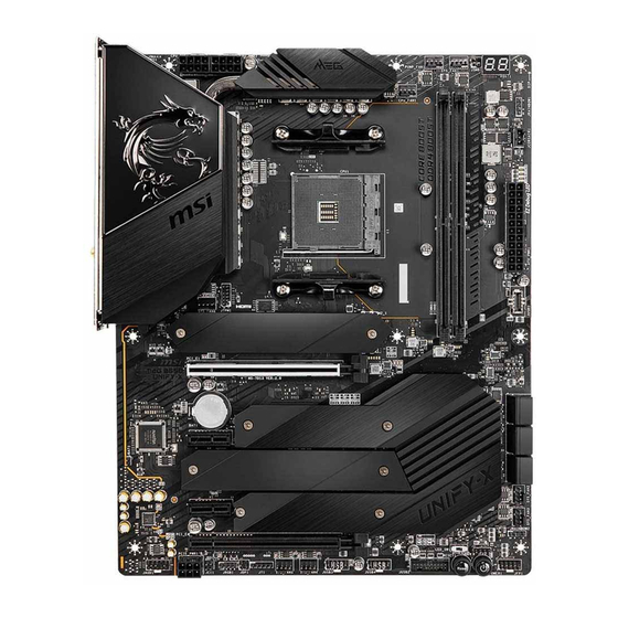
Page 28: Overview Of Components
Overview of Components PUMP_FAN1 SYS_FAN1 CPU_PWR2 CPU_FAN1 Processor Socket CPU_PWR1 JRAINBOW1 JCORSAIR1 ATX_PWR1 JTPM1 JUSB1 SYS_FAN6 DIMMB2 M2_1 DIMMB1 DIMMA2 PCI_E1 DIMMA1 M2_2 SATA ▼ 5 ▲ 6 PCI_E2 SATA ▼ 1 ▲ 2 JBAT1 SATA ▼ 3 ▲ 4 M2_3 SYS_FAN2 PCI_E3... - Page 29 Component Contents Port Name Port Type Page CPU_FAN1, PUMP_FAN1, Fan Connectors SYS_FAN1~6 CPU_PWR1~2, ATX_PWR1, Power Connectors PCIE_PWR1 DIMMA1/A2/B1/B2 DIMM Slots JAUD1 Front Audio Connector JBAT1 Clear CMOS Jumper JCI1 Chassis Intrusion Connector JCORSAIR1 CORSAIR Connector JFP1, JFP2 Front Panel Connectors JRAINBOW1~2 Addressable RGB LED connectors JRGB1...
-
Page 30: Processor Socket
Any attempt to operate beyond product specifications is not recommended. MSI® does not guarantee the damages or risks caused by inadequate operation beyond product specifications. Overview of Components... -
Page 31: Dimm Slots
It is recommended to use a more efficient memory cooling system for full DIMMs ∙ installation or overclocking. The stability and compatibility of installed memory module depend on installed CPU ∙ and devices when overclocking. ∙ Please refer www.msi.com for more information on compatible memory. Overview of Components... -
Page 32: Pci_E1~4: Pcie Expansion Slots
PCI_E4: PCIe 3.0 x16 (Chipset) ⚠ Important If you install a large and heavy graphics card, you need to use a tool such as MSI ∙ Gaming Series Graphics Card Bolster to support its weight to prevent deformation of the slot. - Page 33 ∙ AMD Ryzen 5 3400G & Ryzen 3 3200G) , if you install the MSI M.2 Xpander series add-in card into PCI_E1 slot, only two M.2 slots of the add-in card are available. In CPU mode with AMD Ryzen 4000-G series processors, if you install the MSI M.2 ∙...
- Page 34 M.2 slots with examples of various combination possibilities 1xM.2 PCIe SSD + 6xSATA HDDs 1xM.2 SATA SSD + 6xSATA HDDs M.2 PCIe M.2 SATA 2xM.2 PCIe SSDs + 6xSATA HDDs 1xM.2 SATA SSD + 1xM.2 PCIe SSD + 6xSATA HDDs M.2 PCIe M.2 SATA M.2 PCIe...
- Page 35 4xM.2 PCIe SSDs + 4xSATA HDDs 2xM.2 SATA SSD + 2xM.2 PCIe SSD + 5xSATA HDDs M.2 PCIe M.2 SATA M.2 PCIe M.2 PCIe M.2 PCIe M.2 SATA M.2 PCIe M.2 PCIe For Chipset mode these two For Chipset mode these two PCIe x1 slots are un-available.
-
Page 36: M2_1~4: M.2 Slots (Key M)
M2_1~4: M.2 Slots (Key M) ⚽ Video Demonstration Watch the video to learn how to Install M.2 module. http://youtu.be/JCTFABytrYA M2_1 M2_2 M2_3 M2_4 Installing M.2 module 1. Loosen the screws of M.2 SHIELD FROZR heatsink. 2. Remove the M.2 SHIELD FROZR and remove the protective films from the thermal pads. - Page 37 Standoff Protecting film Thermal pad-1 Thermal pad-2 M.2 Plate 5. Insert your M.2 SSD into the M.2 slot at a 30-degree angle. 6. If the M.2 SSD is shorter than the M.2 SHIELD FROZR heatsink, place the M.2 screw in the notch on the trailing edge of the M.2 module and tighten it into the standoff.
-
Page 38: Sata1~6: Sata 6Gb/S Connectors
SATA1~6: SATA 6Gb/s Connectors These connectors are SATA 6Gb/s interface ports. Each connector can connect to one SATA device. SATA6 SATA2 SATA4 SATA5 SATA1 SATA3 ⚠ Important ∙ Please do not fold the SATA cable at a 90-degree angle. Data loss may result during transmission otherwise. -
Page 39: Jfp1, Jfp2: Front Panel Connectors
JFP1, JFP2: Front Panel Connectors These connectors connect to the switches and LEDs on the front panel. Power LED Power Switch JFP1 Reserved HDD LED Reset Switch HDD LED + Power LED + HDD LED - Power LED - Reset Switch Power Switch Reset Switch Power Switch... -
Page 40: Cpu_Pwr1~2, Atx_Pwr1, Pcie_Pwr1: Power Connectors
CPU_PWR1~2, ATX_PWR1, PCIE_PWR1: Power Connectors These connectors allow you to connect an ATX power supply. CPU_PWR1~2 Ground +12V Ground +12V Ground +12V Ground +12V +3.3V +3.3V +3.3V -12V Ground Ground PS-ON# Ground Ground Ground ATX_PWR1 Ground Ground PWR OK 5VSB +12V +12V +3.3V... -
Page 41: Jusb3~4: Usb 2.0 Connectors
In order to recharge your iPad,iPhone and iPod through USB ports, please install ∙ MSI® DRAGON CENTER utility. JUSB1: USB 3.2 Gen 2 10Gbps Type-C Connector This connector allows you to connect USB 3.2 Gen 2 10Gbps Type-C connector on the front panel. -
Page 42: Jusb2: Usb 3.2 Gen 1 5Gbps Connector
JUSB2: USB 3.2 Gen 1 5Gbps Connector This connector allows you to connect USB 3.2 Gen 1 5Gbps ports on the front panel. Power USB2.0+ USB3_RX_DN USB2.0- USB3_RX_DP Ground Ground USB3_TX_C_DP USB3_TX_C_DN USB3_TX_C_DN USB3_TX_C_DP Ground Ground USB3_RX_DP USB2.0- USB3_RX_DN USB2.0+ Power Ground No Pin... -
Page 43: Cpu_Fan1, Pump_Fan1, Sys_Fan1~6: Fan Connectors
CPU_FAN1, PUMP_FAN1, SYS_FAN1~6: Fan Connectors Fan connectors can be classified as PWM (Pulse Width Modulation) Mode or DC Mode. PWM Mode fan connectors provide constant 12V output and adjust fan speed with speed control signal. DC Mode fan connectors control fan speed by changing voltage. The auto mode fan connectors can automatically detect PWM and DC mode. -
Page 44: Jci1: Chassis Intrusion Connector
JCI1: Chassis Intrusion Connector This connector allows you to connect the chassis intrusion switch cable. Normal Trigger the chassis (default) intrusion event Using chassis intrusion detector 1. Connect the JCI1 connector to the chassis intrusion switch/ sensor on the chassis. 2. -
Page 45: Jbat1: Clear Cmos (Reset Bios) Jumper
JBAT1: Clear CMOS (Reset BIOS) Jumper There is CMOS memory onboard that is external powered from a battery located on the motherboard to save system configuration data. If you want to clear the system configuration, set the jumpers to clear the CMOS memory. Keep Data Clear CMOS/ (default) -
Page 46: Jrgb1: Rgb Led Connector
(12V/G/R/B) with the maximum power rating of 3A (12V). Always turn off the power supply and unplug the power cord from the power outlet ∙ before installing or removing the RGB LED strip. Please use MSI’s software to control the extended LED strip. ∙ Overview of Components... -
Page 47: Jrainbow1~2: Addressable Rgb Led Connectors
(5V). In the case of 20% brightness, the connector supports up to 200 LEDs. Always turn off the power supply and unplug the power cord from the power outlet ∙ before installing or removing the RGB LED strip. ∙ Please use MSI’s software to control the extended LED strip. Overview of Components... -
Page 48: Jcorsair1: Corsair Connector
The JCORSAIR1 connector allows you to connect the CORSAIR Individually Addressable Lighting PRO RGB LED strips 5V or CORSAIR RGB fans with the CORSAIR fan hub. Once all items are connected properly, you can control the CORSAIR RGB LED strips and fans with MSI's software. JCORSAIR1 Data... -
Page 49: Onboard Leds
Onboard LEDs EZ Debug LED These LEDs indicate the debug status of the motherboard. CPU - indicates CPU is not detected or fail. DRAM - indicates DRAM is not detected or fail. VGA - indicates GPU/ PCIE/ M.2 device is not detected or fail. -
Page 50: Hexadecimal Character Table
Hexadecimal Character Table Hexadecimal Debug Code 0 1 2 3 4 5 6 7 8 9 A B C D E F LED display Boot Phases Security (SEC) – initial low-level initialization Pre-EFI Initialization (PEI) – memory initialization Driver Execution Environment (DXE) – main hardware initialization Boot Device Selection (BDS) –... - Page 51 Memory initialization. Configuring memory Memory initialization (other) Memory Installed CPU post-memory initialization is started CPU post-memory initialization. Cache initialization CPU post-memory initialization. Application Processor(s) (AP) initialization CPU post-memory initialization. Boot Strap Processor (BSP) selection CPU post-memory initialization. System Management Mode (SMM) initialization Post-Memory System Agent initialization is started 38 - 3A Post-Memory System Agent initialization (System Agent module specific)
- Page 52 PCI Bus Assign Resources Console Output devices connect Console input devices connect Super IO Initialization USB initialization is started USB Reset USB Detect USB Enable 9E -9F Reserved for future AMI codes IDE initialization is started IDE Reset IDE Detect IDE Enable SCSI initialization is started SCSI Reset...
- Page 53 No Console Input Devices are found Invalid password Error loading Boot Option (LoadImage returned error) Boot Option is failed (StartImage returned error) Flash update is failed Reset protocol is not available S3 Resume Progress Codes S3 Resume is stared (S3 Resume PPI is called by the DXE IPL) S3 Boot Script execution Video repost OS S3 wake vector call...
-
Page 54: Acpi States Codes
ACPI States Codes The following codes appear after booting and the operating system into ACPI modes. System is entering S1 sleep state System is entering S2 sleep state System is entering S3 sleep state System is entering S4 sleep state System is entering S5 sleep state System is waking up from the S1 sleep state System is waking up from the S2 sleep state... -
Page 55: Installing Os, Drivers & Utilities
Installing OS, Drivers & Utilities Please download and update the latest utilities and drivers at www.msi.com Installing Windows® 10 1. Power on the computer. 2. Insert the Windows® 10 installation disc/USB into your computer. 3. Press the Restart button on the computer case. -
Page 56: Uefi Bios
UEFI has many new functions and advantages that traditional BIOS cannot achieve, and it will completely replace BIOS in the future. The MSI UEFI BIOS uses UEFI as the default boot mode to take full advantage of the new chipset’s capabilities. -
Page 57: Bios Setup
BIOS Setup The default settings offer the optimal performance for system stability in normal conditions. You should always keep the default settings to avoid possible system damage or failure booting unless you are familiar with BIOS. ⚠ Important BIOS items are continuously update for better system performance. Therefore, the ∙... -
Page 58: Resetting Bios
Updating BIOS Updating BIOS with M-FLASH Before updating: Please download the latest BIOS file that matches your motherboard model from MSI website. And then save the BIOS file into the USB flash drive. Updating BIOS: 1. Insert the USB flash drive that contains the update file into the USB port. - Page 59 1. Please download the latest BIOS file that matches your motherboard model from the MSI® website. 2. Rename the BIOS file to MSI.ROM, and save it to the root of your USB flash drive. 3. Connect the power supply to CPU_PWR1 and ATX_PWR1. (No need to install CPU and memory.)
-
Page 60: Ez Mode
EZ Mode At EZ mode, it provides the basic system information and allows you to configure the basic setting. To configure the advanced BIOS settings, please enter the Advanced Mode by pressing the Setup Mode switch or F7 function key. Screenshot A-XMP Profile Setup Mode switch... - Page 61 ∙ System information - shows the CPU/ DDR speed, CPU/ MB temperature, MB/ CPU type, memory size, CPU/ DDR voltage, BIOS version and build date. ∙ Boot device priority bar - you can move the device icons to change the boot priority. The boot priority from high to low is left to right.
- Page 62 ▪ To add a BIOS item to a favorite menu 1. Select a BIOS item not only on BIOS menu but also on search page. 2. Right-click or press F2 key. 3. Choose a favorite page and click on OK. ▪...
-
Page 63: Advanced Mode
Advanced Mode Press Setup Mode switch or F7 function key can switch between EZ Mode and Advanced Mode in BIOS setup. BIOS menu BIOS menu selection selection Menu display ∙ BIOS menu selection - the following options are available: ▪ SETTINGS - allows you to specify the parameters for chipset and boot devices. ▪... -
Page 64: Settings Menu
SETTINGS Menu This menu allows you to specify the parameters for system, chipset and boot devices. ▶ System Status sub-menu The System Status sub-menu allows you to set the system clock and view system information. ▶ System Date Sets the system date. Use tab key to switch between date elements. The format is <day>... - Page 65 ▶ Integrated Graphics Configuration sub-menu (optional) Adjusts integrated graphics settings for optimum system. This sub-menu is only available when using the CPU which integrate with IGP. ▶ USB Configuration sub-menu Sets the onboard USB controller and device function. Press Enter to enter the sub-menu.
-
Page 66: Oc Menu
OC Menu This menu allows you to configure the frequencies and voltages for overclocking. Please note that, higher frequency and voltage may benefit overclocking capability but cause system un-stability. ⚠ Important Overclocking your PC manually is only recommended for advanced users. ∙... - Page 67 ▶ DRAM Frequency [Auto] Sets the DRAM frequency. Please note the overclocking behavior is not guaranteed. ▶ Adjusted DRAM Frequency Shows the adjusted DRAM frequency. Read-only. ▶ FCLK Frequency [Auto] Sets the FCLK frequency (Internal Data Fabric clock of DRAM). Please note the overclocking behavior is not guaranteed.
- Page 68 ▶ DRAM Voltages control [Auto] These options allows you to set the voltages related to memory. If set to Auto, BIOS will set these voltages automatically or you can set it manually. ▶ CPU Specifications sub-menu Press Enter to enter the sub-menu. This sub-menu displays the information of installed CPU.
-
Page 69: M-Flash Menu
M-FLASH provides the way to update BIOS with a USB flash drive. Please download the latest BIOS file that matches your motherboard model from MSI website, save the BIOS file into your USB flash drive. And then follow the steps below to update BIOS. -
Page 70: Oc Profile Menu
OC PROFILE Menu ▶ Overclocking Profile 1/ 2/ 3/ 4/ 5/ 6 Overclocking Profile 1/ 2/ 3/ 4/ 5/ 6 management. Press Enter to enter the sub-menu. ▶ Set Name for Overclocking Profile 1/ 2/ 3/ 4/ 5/ 6 Name the current overclocking profile. ▶... -
Page 71: Hardware Monitor Menu
HARDWARE MONITOR Menu This menu allows you to adjust the fan speed manually and monitor CPU/ system voltage. Select a temperature curve line (white) to be showed in Fan operating window Select a fan to be configured Select a fan mode for target fan Click to enable the Smart Fan Smart Fan duty... - Page 72 Adjusting fans 1. Selects a fan that you want to adjust and to display the fan duty curve line (yellow) in fan operating windows. 2. Click and drag the duty points to adjust the fan speed. Select a fan to be adjusted Duty points ⚠...
-
Page 73: Amd Raid Configuration
AMD RAID Configuration The following are the RAID levels supported by RAIDXpert2. RAID 0 (Striping) breaks the data into blocks which are written to separate hard drives. Spreading the hard drive I/O load across independent channels greatly improves I/O performance. RAID 1 (Mirroring) provides data redundancy by mirroring data between the hard drives and provides enhanced read performance. -
Page 74: Initializing Disks
Initializing Disks New disks and legacy disks must be initialized before they can be used to create an AMD-RAID array. Initialization writes AMD-RAID configuration information (metadata) to a disk. ⚠ Important ∙ If a disk is part of an AMD-RAID array, the disk cannot be selected for initialization. To initial the disk anyway, delete the AMD-RAID array. -
Page 75: Creating Arrays
Creating Arrays Arrays can be created after the disks are initialized. ⚠ Important For redundant arrays, the Create process is not started until after the operating ∙ system and AMD-RAID OS drivers have been installed and the system has booted to the operating system. -
Page 76: Deleting Arrays
Deleting Arrays ⚠ Important Deleting an array permanently destroys all data that is on the array. This action ∙ cannot be undone and it is very unlikely that the data can be recovered. ∙ Do not delete the first array listed in the Arrays section, if it is the AMD-RAID bootable array. -
Page 77: Installing Raid Driver
2. When prompted, insert the USB flash drive with AMD RAID Drivers and then click Browse. ▪ To make an AMD RAID Drivers USB flash drive. Insert the MSI Driver Disc into the optical drive. Copy all the contents in \\Storage\AMD\ 3. -
Page 78: Troubleshooting
Troubleshooting Lost BIOS password Before sending the motherboard for RMA repair, try to go over troubleshooting ∙ Clear the CMOS, but that will cause guide first to see if your got similar you to lose all customized settings in the symptoms as mentioned below. - Page 79 European Harmonized Standards. disposing of their end-of-life products. The point of contact for regulatory matters is MSI, y Visit the MSI website and locate a nearby distributor MSI-NL Eindhoven 5706 5692 ER Son. for further recycling information. KC인증서...
- Page 80 MSI la Unión Europea al final de su periodo de vida. Usted will comply with the product take back requirements...
- Page 81 Products designed to be operated del suo ciclo di vita. MSI si adeguerà a tale Direttiva at closer proximities, such as tablet computers, comply with applicable EU requirements in typical ritirando tutti i prodotti marchiati MSI che sono stati venduti all’interno dell’Unione Europea alla fine del...
- Page 82 Copyright © 2020 All rights reserved. contact your place of purchase or local distributor. The MSI logo used is a registered trademark of Alternatively, please try the following help resources Micro-Star Int’l Co., Ltd. All other marks and names for further guidance.
Need help?
Do you have a question about the MEG B550 UNIFY and is the answer not in the manual?
Questions and answers