Table of Contents
Advertisement
proform.com
USER'S MANUAL
Model No. PFEL59718.0
Serial No.
Write the serial number in the space
above for reference.
Serial Number
Decal
ACTIVATE YOUR
WARRANTY
To register your product and
activate your warranty today,
go to my.proform.com.
CUSTOMER CARE
For service at any time, go to
proformservice.com.
Or call 1-888-533-1333
Mon.–Fri. 6 a.m.–6 p.m. MT
Sat. 8 a.m.–12 p.m. MT
Please do not contact the store.
CAUTION
Read all precautions and
instructions in this manual before
using this equipment. Keep this
manual for future reference.
Advertisement
Table of Contents

Related Manuals for Pro-Form COACHLINK E9.0


Summary of Contents for Pro-Form COACHLINK E9.0
- Page 1 proform.com USER’S MANUAL Model No. PFEL59718.0 Serial No. Write the serial number in the space above for reference. Serial Number Decal ACTIVATE YOUR WARRANTY To register your product and activate your warranty today, go to my.proform.com. CUSTOMER CARE For service at any time, go to proformservice.com.
-
Page 2: Table Of Contents
TABLE OF CONTENTS WARNING DECAL PLACEMENT ............. . .2 IMPORTANT PRECAUTIONS . -
Page 3: Important Precautions
IMPORTANT PRECAUTIONS WARNING: To reduce the risk of burns, fire, electric shock, or injury to persons, read all important precautions and instructions in this manual and all warnings on your elliptical before using your elliptical. ICON assumes no responsibility for personal injury or property damage sus- tained by or through the use of this product. - Page 4 1. The elliptical does not have a freewheel; the 3. Over exercising may result in serious injury pedals will continue to move until the fly- or death. If you feel faint, if you become short wheel stops. Reduce your pedaling speed in of breath, or if you experience pain while a controlled way.
- Page 5 STANDARD SERVICE PLANS...
-
Page 6: Before You Begin
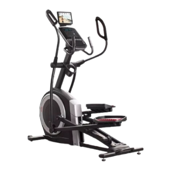
Thank you for selecting the revolutionary PROFORM reading this manual, please see the front cover of this ® COACHLINK E9.0 elliptical. The COACHLINK E9.0 manual. To help us assist you, note the product model elliptical provides an impressive selection of features number and serial number before contacting us. -
Page 7: Part Identification Chart
PART IDENTIFICATION CHART Use the drawings below to identify the small parts needed for assembly. The number in parentheses below each drawing is the key number of the part, from the PART LIST near the end of this manual. The number following the key number is the quantity needed for assembly. -
Page 8: Assembly
ASSEMBLY • To hire an authorized service technician to • In addition to the included tool(s), assembly assemble this product, call 1-800-445-2480. requires the following tools: one Phillips screwdriver • Assembly requires two persons. two adjustable wrenches • Place all parts in a cleared area and remove the packing materials. - Page 9 3. With the help of a second person, place some of the packing materials (not shown) under the front of the Frame (1). Have the second per- son hold the Frame to prevent it from tipping while you complete this step. If there are shipping supports attached to the front of the Frame (1), remove the screws from the shipping supports, and discard the screws...
- Page 10 5. Tip: Avoid pinching the Upper Wire (110). Have a second person hold the Upright (4) on the Frame (1). Avoid pinching the Upper Wire (110) Tip: Two M10 x 25mm Screws (92) are preattached to the Frame (1). Attach the Upright (4) to the Frame (1) with two additional M10 x 25mm Screws (92);...
- Page 11 7. Apply grease to the axle on the right side of the Upright (4). Next, slide a Pivot Spacer (54) onto the right side of the Upright (4). 4 Grease Then, identify the Right Upper Body Leg (60), orient it as shown, and slide it onto the right side of the Upright (4).
- Page 12 9. Apply grease to a Pedal Arm Axle (64). Insert the Pedal Arm Axle (64) into the Right Upper Body Leg (60) and the Right Pedal Arm (58) from the direction shown. Next, slide an M8 x 22mm Washer (129) onto an M8 x 13mm Screw (82), and tighten the Screw a few turns into the Pedal Arm Axle (64).
- Page 13 11. Orient the Rear Console Cover (80) as shown, and attach it to the Upright (4) with two M4 x 16mm Screws (101). Then, orient the Front Console Cover (79) as shown, and attach it to the Rear Console Cover (80) with two M4 x 16mm Screws (101).
- Page 14 14. Identify the Right Upper Body Arm (61), orient it as shown, and insert it into the Right Upper Body Leg (60). Attach the Right Upper Body Arm (61) with two M8 x 45mm Bolts (96) and two M8 Locknuts (102);...
- Page 15 17. Orient the Right Arm Front and Rear Covers (65, 66) around the Right Upper Body Leg (60) as shown, and then attach them with two M4 x 16mm Screws (101). Repeat this step on the other side of the elliptical.
-
Page 16: How To Use The Elliptical
HOW TO USE THE ELLIPTICAL HOW TO PLUG IN THE POWER CORD A temporary adapter may 2-pole Receptacle This product must be grounded. If it should mal- be used to function or break down, grounding provides a path of connect the Adapter least resistance for electric current to reduce the risk power cord... - Page 17 HOW TO MOVE THE ELLIPTICAL HOW TO LEVEL THE ELLIPTICAL Due to the size and weight of the elliptical, moving If the elliptical rocks slightly on your floor during use, it requires two persons. Stand in front of the elliptical, turn one or both of the leveling feet (D) beneath the hold the upright (A), and place one foot against one of rear of the frame or turn the leveling foot (E) under...
- Page 18 HOW TO EXERCISE ON THE ELLIPTICAL To mount the elliptical, hold the handlebars (G) or the upper body arms (H) and step onto the pedal (I) that is in the lower position. Then, step onto the other pedal. Push the pedals until they begin to move with a con- tinuous motion.
- Page 19 CONSOLE DIAGRAM FEATURES OF THE CONSOLE The console also offers a selection of onboard work- outs. Each onboard workout automatically changes the IMPORTANT: To activate your console and begin resistance of the pedals and prompts you to maintain using its exclusive features, see assembly step 19 a target pedaling speed as it guides you through an on page 15.
- Page 20 HOW TO TURN ON THE POWER HOW TO USE THE MANUAL MODE IMPORTANT: If the elliptical has been exposed to 1. Begin pedaling or press any button on the cold temperatures, allow it to warm to room tem- console to turn on the console. perature before you turn on the power.
- Page 21 Calories per Hour (CALS/HR)—The approximate To manually advance the scan cycle, press the number of calories you are burning per hour. Multi-scan button (B) repeatedly. Resistance (RESIST)—The resistance level of the To turn off the scan mode, press the Display pedals.
- Page 22 5. Measure your heart rate if desired. When your pulse is detected, your heart rate will be shown in the display. For the most accurate heart You can measure your heart rate using either rate reading, hold the contacts for at least 15 seconds.
- Page 23 HOW TO USE AN ONBOARD WORKOUT appear in the display, increase your pedaling speed. When the words TOO FAST appear, 1. Begin pedaling or press any button on the decrease your pedaling speed. When no words console to turn on the console. appear, maintain your current pedaling speed.
- Page 24 HOW TO USE THE SOUND SYSTEM HOW TO CONNECT YOUR TABLET TO THE CONSOLE To play music or audio books through the console sound system while you exercise, plug a 3.5 mm male The console supports BLUETOOTH connections to to 3.5 mm male audio cable (not included) into the tablets via the iFit Bluetooth Tablet app and to compat- jack on the console and into a jack on your personal ible heart rate monitors.
- Page 25 5. Disconnect your tablet from the console if HOW TO CHANGE CONSOLE SETTINGS desired. 1. Select the settings mode. To disconnect your tablet from the console, first select the disconnect option in the iFit Bluetooth If you are using the manual mode or an onboard Tablet app.
- Page 26 Unit of Measurement—The currently selected Contrast Level—The currently selected con- unit of measurement will appear in the display. The trast level will appear in the display. Press the console can show speed and distance in standard Resistance increase and decrease buttons to or metric units of measurement.
-
Page 27: Fcc Information
FCC INFORMATION This equipment has been tested and found to comply with the limits for a Class B digital device, pursuant to Part 15 of the FCC Rules. These limits are designed to provide reasonable protection against harmful interference in a residential installation. This equipment generates, uses, and can radiate radio frequency energy and, if not installed and used in accordance with the instructions, may cause harmful interference to radio communications. -
Page 28: Maintenance And Troubleshooting
MAINTENANCE AND TROUBLESHOOTING MAINTENANCE HOW TO ADJUST THE REED SWITCH Regular maintenance is important for optimal If the console does not display correct feedback, the performance and to reduce wear. Inspect and properly reed switch should be adjusted. To adjust the reed switch, first unplug the power cord. - Page 29 HOW TO ADJUST THE DRIVE BELT Next, locate and loosen the If the pedals slip while you are pedaling, even while Idler Screw (89). the resistance is adjusted to the highest level, the drive Tighten the Drive belt may need to be adjusted. To adjust the drive belt, Belt Adjustment first unplug the power cord.
-
Page 30: Exercise Guidelines
EXERCISE GUIDELINES Burning Fat—To burn fat effectively, you must exer- WARNING: cise at a low intensity level for a sustained period of Before beginning this time. During the first few minutes of exercise, your or any exercise program, consult your physi- body uses carbohydrate calories for energy. -
Page 31: Part List
PART LIST Model No. PFEL59718.0 R0118C Key No. Qty. Description Key No. Qty. Description Frame/Ramp Roller Rear Stabilizer Left Pedal Handle Access Cover Axle Cover Upright Pivot Spacer M4 x 19mm Screw Retainer Front Stabilizer Roller Arm Bushing Console Large Arm Bearing Roller Guide Right Pedal Arm Crank Bearing Spacer... - Page 32 Key No. Qty. Description Key No. Qty. Description M4 x 16mm Screw Frame Bushing M8 Locknut M10 x 47mm Bolt M6 x 12mm Screw Small Arm Bearing M10 x 114mm Screw M4 x 16mm Machine Screw M4 x 25mm Flange Screw Right Upper Grip Lower Ramp Cover M4 x 25mm Screw...
-
Page 33: Exploded Drawing
EXPLODED DRAWING A Model No. PFEL59718.0 R0118C... - Page 34 EXPLODED DRAWING B Model No. PFEL59718.0 R0118C...
- Page 35 EXPLODED DRAWING C Model No. PFEL59718.0 R0118C...
-
Page 36: Ordering Replacement Parts
ORDERING REPLACEMENT PARTS To order replacement parts, please see the front cover of this manual. To help us assist you, be prepared to provide the following information when contacting us: • the model number and serial number of the product (see the front cover of this manual) •...
Need help?
Do you have a question about the COACHLINK E9.0 and is the answer not in the manual?
Questions and answers
can i buy new bearings for my machine if not what are the sizes proform e9.0