Videotec MAXIMUS MMX Instruction Manual
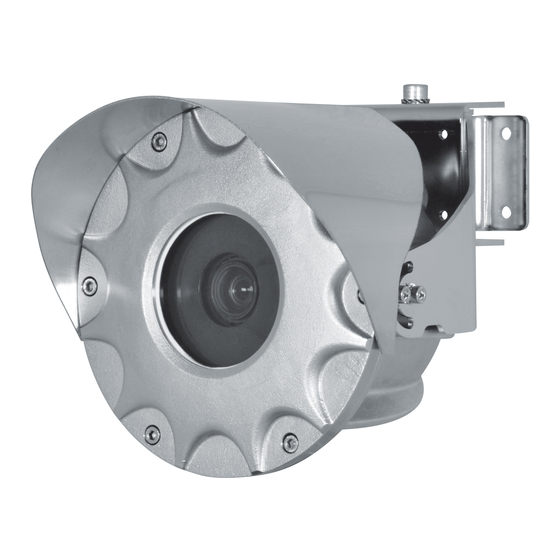
Flameproof full hd camera in a compact design
Hide thumbs
Also See for MAXIMUS MMX:
- Instruction manual (214 pages) ,
- Instruction manual (88 pages) ,
- Instruction manual (88 pages)

Related Manuals for Videotec MAXIMUS MMX


Summary of Contents for Videotec MAXIMUS MMX
- Page 1 ENGLISH MAXIMUS MMX Flameproof FULL HD camera in a compact design English - Instruction manual...
-
Page 3: Table Of Contents
Contents E N G L I S H 1 About this manual ........................5 1.1 Typographical conventions ..............................5 2 Notes on copyright and information on trademarks ............5 3 Safety rules ..........................6 4 Product description and type designation ................8 4.1 Product overview ................................... - Page 4 8.2 Web interface ..................................22 8.2.1 First access to the web pages ................................22 8.2.2 Inserting an SD Card ....................................22 9 Maintenance ...........................23 9.1 Routine maintenance ................................23 9.1.1 Inspecting the cables ...................................23 9.2 Extraordinary maintenance .............................23 9.2.1 Fuses replacement ....................................23 9.2.2 Replacing the gasket ...................................24 9.2.3 Factory Default ......................................24 10 Cleaning ..........................25 10.1 Cleaning the glass window ............................25...
-
Page 5: About This Manual
For greater certainty, the use of "manufacturer" in The mentioned names of products or companies are this manual means "VIDEOTEC s.r.l.". trademarks or registered trademarks. 1.1 Typographical conventions Pelco, the Pelco logo, and other trademarks... -
Page 6: Safety Rules
3 Safety rules • A power disconnect device must be included in the electrical installation, and it must be very quickly recognizable and operated if needed. DANGER! • The electrical system to which the unit is Explosion hazard. connected must be equipped with a 10A max Read carefully to avoid danger of automatic bipolar circuit breaker. - Page 7 • Since the user is responsible for choosing the • Only use original VIDEOTEC spare parts. Strictly surface to which the unit is to be anchored, we adhere to the maintenance instructions attached do not supply the fixing devices for attaching the to each replacement kit.
-
Page 8: Product Description And Type Designation
4 Product description and 4.1 Product overview type designation The main parts of the product are illustrated below. 01. Fastening support. The MMX flameproof housing was designed for 02. Reinforcement support. installation in potentially explosive environments, manufactured in AISI 316L shot peened and 03. -
Page 9: Range Of Use
4.2 Range of use 4.4 Gas Group, Dust Group and Temperatures The unit is designed for use in a fixed location, for surveillance of areas classified as zone 1-21 and zone The device is certified for group IIB (Gas) and group 2-22 with potentially explosive atmospheres. -
Page 10: Product Marking Label
4.6 Product marking label Fig. 2 Number of the accredited body providing ATEX marking. The Class temperature depends quality evaluation. on the electronics installed inside and the ambient temperature. Manufacturer’s name and address. IECEX marking. The Class temperature depends Model. on the electronics installed inside and the Ambient temperature of use. -
Page 11: For Ul/Csa Standard Reference Only
4.7 For UL/CSA standard reference only. The flameproof joints are not intended to be repaired. In the USA, the National Electrical Code (NEC) and in Canada the Canadian Electrical Code (CEC) apply to electrical equipment used on hazardous industrial premises. These Codes contain the installation regulations for electrical facilities in all areas and refer to a number of further standards of other institutions with specifications for the construction and installation of suitable equipment. -
Page 12: Connections
Connections The choice of connection must comply with local legislation in force. Cable glands:select a cable gland in compliance with UL2225 with the following protection AEx d IIC and C22.2 with the following protection Ex d IIC in compliance with the marking of the product. Conduit:it is necessary to install a sealing device within 50mm of the product input when the conduit is used. -
Page 13: Model Identification
Cable gland Ex d 1/2" NPT and 4m (13ft) armoured cable Cable gland Ex d 1/2" NPT and 10m (32.8ft) armoured cable Tab. 2 MAXIMUS MMX - CERTIFICATIONS AND MARKINGS (WITH CABLE) Certification Marking Ambient temperature Cable input tempe- rature ATEX II 2 G Ex db IIB T6...T5 Gb... -
Page 14: Preparing The Product For Use
5 Preparing the product for 6 Installation Before carrying out any type of intervention, read the "Safety rules" Before carrying out any type of chapter of this manual. intervention, read the "Safety rules" We strongly recommend using only approved chapter of this manual. brackets and accessories during installation. -
Page 15: Installation Options
6.1 Installation options The M8 axis must always be in the vertical position. The brackets supplied allow installation of the product in the positions illustrated below. Fig. 7 Example of ceiling installation, vertical rotation, -90°. Fig. 4 Example of wall installation, vertical rotation, -90°. Fig. -
Page 16: Fixing To Parapet Or Ceiling Mount
6.1.1 Fixing to parapet or ceiling mount The product can be installed on a parapet or on the ceiling. Fasten the fastening support (01) to its final installation surface. Tighten the screws. Attach the reinforcement support (02) to the housing support (03) using the M5 screws and the 5 washers supplied. -
Page 17: Wall Mounting
6.1.2 Wall mounting The product can be installed on a wall. Fasten the fastening support (01) to its final installation surface. Tighten the screws. Attach the housing support (03) to the fastening support (01) using the M8 screw (05), washers and nut. -
Page 18: Housing Opening
6.3 Housing opening 6.5 Housing board description BOARD DESCRIPTION Before carrying out any type of intervention, read the "Safety rules" Connector/ Function Terminal chapter of this manual. Power supply line (24Vac/24Vdc) Unscrew the fastening screws and remove the front Heater cover from the housing body. -
Page 19: Connecting The Power Supply
6.6 Connecting the power supply Maximum Ethernet cable length (category 5E): 100m. 6.6.1 Connecting the power supply, 24Vac/24Vdc (version of the product The PSE (Power-Supplying Equipment) devices suitable for the product power supply must comply not cabled) with the standard IEEE 802.3at (PoE+). Check that the power supply socket and The Ethernet cable should be connected to cable are adequately dimensioned. -
Page 20: Connection Of The Ethernet Cable
6.7 Connection of the Ethernet 6.8 Earthing equipotential cable connection The equipotential connection must be carried out The Ethernet cable shield must always be using an external cable with a minimum 4mm² earthed via the connector. Always use a section (11AWG). shielded RJ45 connector. -
Page 21: Housing Closure
6.9 Housing closure Insert the front cover in the housing body, keeping the closure holes between the cover and the body aligned. Test system operation for positive results before closing the product and allowing Be very careful not to damage the O-ring the presence of a hazardous atmosphere. -
Page 22: Switching On
7 Switching on 8.2 Web interface 8.2.1 First access to the web pages Ensure the unit and the other components of the system are appropriately closed to The first operation in configuring the device consists prevent contact with live parts. in connecting to the web interface. -
Page 23: Maintenance
The fuse must only 9.1 Routine maintenance be replaced by qualified staff. When contacting VIDEOTEC for assistance please To maintain cULus Listed certification, the provide the serial number and the identification fuse must be UL Listed (OMEGA GT520222, code of the model. -
Page 24: Replacing The Gasket
9.2.2 Replacing the gasket 9.2.3 Factory Default Replace the O-ring gasket of the product with the It is possible to reset to the factory default settings. one supplied. The effect of the Factory Default procedure is Open and close the cover as described in the the same as restoring the factory default settings chapters above. -
Page 25: Cleaning
10 Cleaning 11 Information on disposal and recycling Before carrying out any type of intervention, read the "Safety rules" The European Directive 2012/19/EU on Waste chapter of this manual. Electrical and Electronic Equipment (WEEE) mandates that these devices should not be disposed Frequency will depend on the type of of in the normal flow of municipal solid waste, but environment in which the product is used. -
Page 26: Troubleshooting
12 Troubleshooting 13 Technical data 13.1 Mechanical Before carrying out any type of intervention, read the "Safety rules" AISI 316L stainless steel construction chapter of this manual. External shot peened and electro-polished surfaces Contact an authorized support centre Sunshield if the problems listed below persist or Supports for wall, ceiling or parapet installation you have any other issues that are not Unit weight:... -
Page 27: Cameras
13.6 Cameras 13.7 Environment Day/Night Full HD 3x For indoors and outdoors installation Resolution: 6mp - (16:9) 3200 x 1800 (3:2) 3072 x 2048 Certification temperature: from -40°C (-40°F) up to +65°C (149°F) (T6/T85°C) or +70°C (158°F) (T5/T100°C) Max image rate: 1080p/30fps Operating temperature: Image Sensor: 1/1.8”... -
Page 28: Certifications
13.8 Certifications 13.9 Certifications - Explosion- proof applications Electrical safety (CE): EN60950-1, IEC60950-1, EN62368-1, IEC62368-1 ATEX (EN IEC 60079-0, EN 60079-1, EN 60079-31) Electromagnetic compatibility (CE): EN61000-6-4, IECEx (IEC 60079-0, IEC 60079-1, IEC 60079-31) EN61000-3-2, EN61000-3-3, EN50130-4, EN55032 EAC EX (TR CU 012/2011) (Class A) INMETRO (ABNT NBR IEC 60079-0, ABNT NBR IEC RoHS (CE): EN IEC 63000... -
Page 29: Technical Drawings
14 Technical drawings The indicated measurements are expressed in millimetres. WALL MOUNTING PARAPET OR CEILING MOUNTING Fig. 29 MAXIMUS MMX. MNLCMMX_2222_EN... - Page 30 Headquarters Italy VIDEOTEC s.r.l. Via Friuli, 6 - I-36015 Schio (VI) - Italy Tel. +39 0445 697411 - Fax +39 0445 697414 Email: info@videotec.com www.videotec.com MNLCMMX_2222_EN...
Need help?
Do you have a question about the MAXIMUS MMX and is the answer not in the manual?
Questions and answers