
Related Manuals for ECKELMANN Virtus 5 Series


Summary of Contents for ECKELMANN Virtus 5 Series
- Page 1 Operating instruction System Centre Virtus 5 series The central of the E*LDS system The series includes the following expansion stages: VSC 5010 / VSC 5110 / VSC 5410 / VSC 5510 Firmware V7.16.x 16.05.2023 Docu 2.0...
- Page 2 Copyright: All rights to any use whatever, utilisation, further development, forwarding and creation of copies remain with the Eckelmann AG company. In particular, neither the contract partners of Eckelmann AG nor other users have the right to distribute or market the IT programs/program parts or modified or edited versions without express written permission.
-
Page 3: Table Of Contents
Connections in the complete design....................16 3.3.1 Communication interfaces........................18 Version dependencies for other E*LDS components ...............19 System centre functions........................20 Tasks and functions ..........................20 Expansion stages of the Virtus 5 series ....................21 Function of System Centre........................23 Starting characteristics ........................23 5.1.1 First start - Reset System........................23 5.1.2 Restart - Restart of the controller ......................23... - Page 4 M-bus Interface for Consumption Data Capture ................36 Alarms and messages .........................37 5.8.1 Explanation of terms for "Alarms and Messages" ..................39 5.8.2 Acknowledgement of alarms and messages..................39 5.8.3 Priority concept............................40 5.8.4 Remote alarm signalling.........................41 5.8.4.1 EASY alarm destinations 1..3.........................41 5.8.4.2 Extended alarm destinations 4..15 ......................42 5.8.5 Automatic transmission of alarms via Pushover..................44 5.8.6...
- Page 5 6.12 Battery replacement..........................70 6.13 Firmware Update ..........................72 6.13.1 Performing firmware update ........................73 System centre and SIOX connection / terminal assignment ............75 System centre terminal diagram......................75 7.1.1 Terminal assignment of the 230 V AC power supply ................76 7.1.2 Terminal assignment of the 230 V AC digital inputs ................77 7.1.3 Terminal assignment of the 230 V relay outputs ..................78 7.1.4...
- Page 6 Specifications of System Centre and SIOX ..................176 12.1 Electrical data .............................176 12.2 Mechanical data..........................178 12.2.1 Dimensions............................178 12.2.2 Control panel cut-out ..........................179 12.2.2.1 Mounting frame for control panel installation..................180 12.3 Information on open source software ....................181 Order numbers and accessories of System Centre................182 13.1 System centre and SIOX........................182 13.2...
-
Page 7: Conventions
1 Conventions 1.1 Warning signs, symbols and text formatting used in this manual Explanation of the warning signs, symbols and text formatting used in this operating and service manual: • DANGER DANGER Instructions with this symbol and/or the signal word DANGER warn the user of situations that will cause severe injury or death if the specified instructions are not observed! * •... -
Page 8: Explanation Of Text Formatting
A general instruction consists of two elements: The symbol with text (including NOTICE, if applicable) and the text of the instruction: For example: NOTICE The current operating manual is available online from the E°EDP (Eckelmann ° Electronic Documentation Platform) at www.eckelmann.de/elds. Firmware V7.16.x 16.05.2023 8/183... -
Page 9: Safety Information
2 Safety Information This operating manual is part of the device. It must be kept in the vicinity of the controller as well as for future use so that it can be consulted when required. The operating manual must be available to the operating and maintenance personnel at all times in order to avoid operating errors. -
Page 10: Exclusion Of Liability For Non-Observance
ATTENTION Warning of damage to goods! In our experience, the transmission of fault messages is not yet functional during the putting into service (no internet connection, no telephone line installed, etc.). It is strongly recommended in such cases to monitor the controller via the CAN bus using a system centre, a store computer or an operator terminal and to enable the transmission of fault messages, for example using a GSM modem via a mobile telephone system. -
Page 11: Intended Use
2.3 Intended Use The controller is exclusively intended for the following use: The controllers in the Virtus 5 series are intended for use as system centre of the E*LDS system in commercial and industrial refrigeration systems and building automation with the scope of functions and in accordance with the environmental conditions described in this operating manual. -
Page 12: Electrostatic-Sensitive Components And Control Components (Esd)
Containers and worktops made of wood, metal or conductive plastics or paper bags 2.6 Abbreviations used • DGUV Regulation 3 - Accident Prevention Regulation for Electrical Systems and Equipment (previously: BGV A3 - Employer’s Liability Association Regulation for Occupational Health and Safety) • DIN Deutsches Institut für Normung e.V. (German Standardisation Institute) • E°EDP/EDP Electronic Documentation Platform of Eckelmann AG • ESD Electrostatic-Sensitive Device • ESD Electro-static discharge (Electro Sensitive Devices) • IEC International Electric Committee •... -
Page 13: System Centre System Design
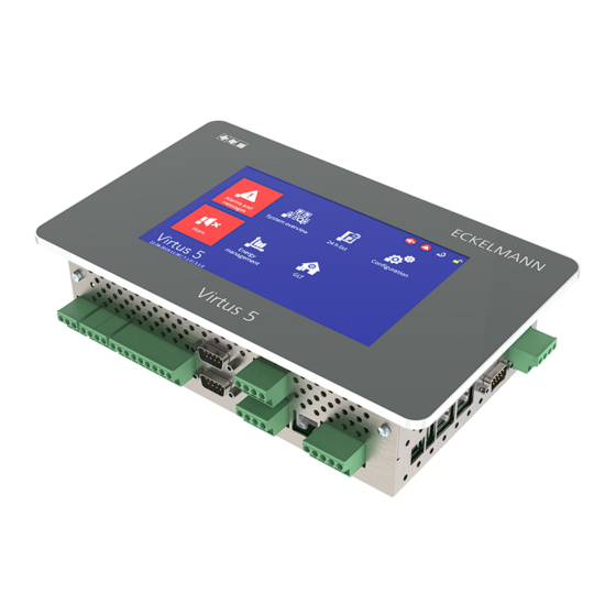
The main feature differences are described in more detail in chapter Expansion stages of the Virtus 5 series. Virtus 5 series system centre with touchscreen. 3.1 Application The system centres in the Virtus 5 series are intended for installation in control panels. They are available in various expansion stages and their range of functions is enabled using licence codes. The system centres include the following models: VSC 5010 / VSC 5110 / VSC 5410 / VSC 5510;... - Page 14 https://edp.eckelmann.de/edp/lds/_S88KwDvR7a Firmware V7.16.x 16.05.2023 14/183...
- Page 15 The system centre (complete design) in the E*LDS system: The system centres in the Virtus 5 series are compatible with the CI 5x00/CI 4x00/CI 3x00 and are intended as replacement device for these predecessor models. The CI 4000 series does not have any direct interfaces to the old LDS1 system (VS 1000 / VS 2000...
-
Page 16: Upgrade Scenarios
4-1-12 - System Upgrade. Licence key required. The licence key is provided by Eckelmann AG and must be paid for. In this case, please contact your account manager. 3.3 Connections in the complete design Inputs and outputs - bottom •... - Page 17 Interfaces - bottom • SIOX: 1 x COMBICON terminal 91..95 (power supply) and 1 x RJ45 port (data cable) for connecting up to max. 4 optional SIOX extension modules. • COM1 / GSM modem port for remote access via modem using a host system or the connection of a service PC for serial direct cable connection •...
-
Page 18: Communication Interfaces
3.3.1 Communication interfaces Interface Type Function VSC 5410 VSC 5510 VSC 5010 VSC 5110 CAN bus 1 COMBICON • First CAN bus segment (terminals 1..4) CAN bus 2 COMBICON • Second CAN bus segment (terminals 21..24) COM1 / MODEM RS232 •... -
Page 19: Version Dependencies For Other E*Lds Components
• LDSWin Complete range of functions: from Version V2.4.9.4131 or higher. Current information can be found at www.eckelmann.de/ldswin.. • AL 300 Operator Terminal If a system centre is present in the E*LDS system, the AL 300 operator terminals with the following version must be used: ... -
Page 20: System Centre Functions
4 System centre functions 4.1 Tasks and functions Functions starting with VSC 5010 / VSC 5110 and higher • Central parametrisation and configuration of all E*LDS components via the CAN bus / Modbus: all E*LDS components can be operated and configured remotely via the controller (see operating manual "Basics and general security and connection instructions"). -
Page 21: Expansion Stages Of The Virtus 5 Series
4.2 Expansion stages of the Virtus 5 series On the hardware side, the controller is always supplied in the complete design; on the software side, the individual expansion stages and the associated range of functions are enabled using a licence key, see chapter Menu 4-1-12 - System Upgrade. - Page 22 VSC 5410 + CAN bus repeater - successor for CI 4500 / CI 5500 It is possible to upgrade at any time, for example from VSC 5410 to VSC 5510. Only a new licence key that can be obtained from Eckelmann AG has to be entered for this in the menu 4-1-12. The part numbers of the individual expansion stages are listed in chapter System centre part numbers and accessories.
-
Page 23: Function Of System Centre
5 Function of System Centre 5.1 Starting characteristics The following are distinguished for any start-up of the controller: • First start - Reset System • Restart - Restart of the controller 5.1.1 First start - Reset System ATTENTION Risk of loss of data and the configuration! All saved data and configurations of the system centre are irrevocably lost during deletion of the archives (operating and energy data), the alarm and... -
Page 24: Configuration Of The E*Lds System Using The Ldswin Pc Software
5.2 Configuration of the E*LDS system using the LDSWin PC software The system centre and all components connected to it can be conveniently configured using a PC with the LDSWin PC software. This also includes the possibility to read out the configurations of all components and store them on the PC ("Save parameter sets"... -
Page 25: Can Bus Station Monitoring
VS 3010 / VS 3010 BS / VS 3010 CT / VS 3010 WP / FS 3010 / VS 300 / VS 3010 C / VS 3015 C / VS 3015 CT System centre of the Virtus 5 series 1 system centre and 1 integrated LAN gateway AL 300 operator terminal 112 .. -
Page 26: Alarm Suppression During Manual Shutdown Of Case Controllers
5.3.1 Alarm suppression during manual shutdown of case controllers If a case controller is switched off, e.g. for cleaning purposes, or it has failed,, this is detected as failed by the station monitoring. The following symbol is then shown in the status bar at the top right in the display of the system centre: ... -
Page 27: Integration Of Case Controllers Of The E*Lds System
5.4.1 Integration of case controllers of the E*LDS system The following case controllers can be integrated and archived in the E*LDS system via Modbus: Connection to the system centre is made via the COM3 / Modbus interface. For detailed information, see chapter Connection of case controllers to Modbus. -
Page 28: Integration Of External Controllers
5.4.2 Integration of external controllers The following external controllers can be integrated and archived in the E*LDS system. Furthermore, the temperature archives (see Menu 4-2) of the following controllers can be viewed in the system centre. Compact case controller with Dixell controller Connection to the system centre is made via the COM3 / Modbus interface. -
Page 29: Digital Inputs
48 digital inputs (12 digital inputs for each SIOX module, see Menu 4-1-1), for see details see chapter SIOX – Terminal assignment of the 230 V AC digital inputs. SIOX operating instructions Comprehensive details on the SIOX extension modules and their current operating instructions can be found here: https://edp.eckelmann.de/edp/lds/_S88KwDvR7a Firmware V7.16.x 16.05.2023 29/183... -
Page 30: Alarm And Message Inputs
5.5.1 Alarm and message inputs Configuration Digital inputs are available for recording alarms and messages. These are disabled at the factory and must be configured in Menu 4-1-2 before use so that they operate either according to the quiescent current or the operating current principle. -
Page 31: Special Inputs
5.5.2 Special inputs Configuration Digital inputs are available for the use of special functions. These are initially disabled and must be configured before use (Menu 4-1-3). Detailed information about the configuration can be found in the chapter Alarm and message inputs. -
Page 32: Relay Outputs
4-1-1), for details see chapter SIOX - Terminal assignment of the 230 V AC relay outputs. SIOX operating instructions Comprehensive details on the SIOX extension modules and their current operating instructions can be found here: https://edp.eckelmann.de/edp/lds/_S88KwDvR7a Firmware V7.16.x 16.05.2023 32/183... -
Page 33: Alarm Relays Prio1 / Prio2
5.6.1 Alarm relays PRIO1 / PRIO2 The system controller has two floating relay contacts for the fixed alarm priorities X1 and X2 (terminal PRIO1: 35/36/38 and PRIO2: 25/26/28, see chapter Terminal assignment of the 230 V AC relay outputs). -
Page 34: Multi-Function Relay Aux
5.6.2 Multi-function relay AUX Configuration In addition to the prioritised Alarm relays PRIO1 / PRIO2 ones, the controller also has the changeover contact AUX (terminals 15/16/18, see chapter Terminal assignment of the 230 V AC relay outputs). The relay output can be configured via Menu 4-1-7 (Other) with any of the following parameters for these functionalities: ... -
Page 35: Relay Outputs For Week Timers
5.6.3 Relay outputs for week timers By using up to a maximum of 4 SIOX extension modules (see chapter SIOX - connection to the controller), the number of relay outputs can be increased by another 32 (8 relay outputs for each SIOX module, see Menu 4-1-1). -
Page 36: M-Bus Interface For Consumption Data Capture
New measuring points connected to the M-bus are found using a scan process and included in the system. The scan process is started in menu 4-1-6 using the following button: If new measuring points have been found by the scan process, these are then displayed in the list and can be configured. An overview of the supported M-bus meters can be found here: https://edp.eckelmann.de/edp/lds/_dGFHqz89xb Firmware V7.16.x 16.05.2023 36/183... -
Page 37: Alarms And Messages
5.8 Alarms and messages ATTENTION Risk of failure of the alarm paths or alarm forwarding! In systems with highly disrupted CAN bus communication (frequent messages of CAN faults or even CAN failures), it is not ensured that E*LDS components can successfully forward their alarms. - Page 38 In addition to the two OFF-delay alarm relays PRIO1 (1, 11, 21,...91) and PRIO2 (2, 12, 22,...92), any alarm priority can be assigned to the multi-function relay AUX (e,g. parameter PrioX3 for 3, 13,..93 or PrioX8 for 8, 18,..98).
-
Page 39: Explanation Of Terms For "Alarms And Messages
5.8.1 Explanation of terms for "Alarms and Messages" The following terms are used in connection with alarms and messages in this operating manual: • receive time stamp ("incoming"): date with time of the alarm / message when this occurred (arrived). •... -
Page 40: Priority Concept
5.8.3 Priority concept Possible priorities for alarms and messages are --, 0, 1, 2 to 99. This priority range is divided into 10 alarm groups (decades 0..9): Priorities Function No message is generated, no alarm is signalled 0, 10, 20,...90 Lowest priority, message entry only in the message list, no alarm is signalled 1, 11, 21,...91 High priority alarm - entry in alarm and message lists, remote alarm is signalled, local... -
Page 41: Remote Alarm Signalling
5.8.4 Remote alarm signalling There are 15 alarm destinations (3 EASY alarm destinations and 12 extended alarm destinations; see chapter Menu 4-1-7 - Alarm Signalling) available for remote alarm signalling. These destinations can be: • A PC with the PC software LDSWin •... -
Page 42: Extended Alarm Destinations 4
5.8.4.2 Extended alarm destinations 4..15 The extended alarm destinations provide significantly more options for differentiated remote alarm signalling as compared with EASY alarm destinations. The extended alarm destinations 4..15 are only displayed (read-only) in the system centre and can only be edited using the LDSWin PC software. - Page 43 In order to illustrate the priority concept and the decades (priority groups), these are listed in the following table and explained using examples: Vertical : Maintenance-group-dependent allocation of alarm priorities Horizontal: priority groups X0..X9 in decades Refrigeration pack Heating …...
-
Page 44: Automatic Transmission Of Alarms Via Pushover
5.8.5 Automatic transmission of alarms via Pushover The controller provides the possibility to automatically forward alarms and messages in plain text from the E*LDS system via the "Pushover" message service (Menu 4-1-7). A user account must be created at "Pushover"... -
Page 45: Automatic Transmission Of Alarms Via Gsm Modem
5.8.7 Automatic transmission of alarms via GSM modem The controller provides the possibility to automatically forward alarms and messages in plain text from the E*LDS system via a modem to various destinations (Menu 4-1-7). The following information is transmitted in the message: •... -
Page 46: Service Mode
5.8.8 Service Mode During maintenance or service work on refrigeration pack systems, a series of alarms and messages is tripped whose forwarding to a control centre or fault service is not required. The controller can be put into the Service Mode for this purpose. -
Page 47: Energy Management
5.9 Energy management If the digital inputs of the system centre and/or those of any of its SIOX extension modules for energy management are configured as pulse measuring points (Menu 4-1-6) or M-bus measuring points are used (Menu 4-1-6), energy consumption, capacity, water or gas consumption etc. can be recorded, see chapter Calculation of consumption / power from meter values. - Page 48 Each load shedding stage can be configured with the following parameters. Shed load of the stage The maximum electrical capacity of the stage must be configured using parameters (Leistung). The calculation of the stages to be shed is performed based on this parameter. Stages whose shed load has been parametrised to 0 are also shed according to their prioritisation (order).
-
Page 49: Calculation Of Consumption / Power From Meter Values
The following diagram gives an overview of how the load management affects the various consumers and on which paths the LSM and the consumers can communicate with each other via the CAN bus. 5.9.2 Calculation of consumption / power from meter values Settings on the controller For the calculation of consumption and power using meter values of energy and quantity meters, the meter constant and transformer constant in the controller must be set in Menu 4-1-6. - Page 50 The basis for calculating consumption and power is explained in more detail below using an example: Meter constant: 1000 pulses/kWh Transformer constant: 20 (corresponds to the conversion ratio 100:5 of the current transformer) Number of measured pulses: e.g. 600 pulses Time of the pulse counting: e.g.
-
Page 51: Eu Archives (Haccp)
5.10 EU archives (HACCP) Using the Menu 2-6 in the system centre, it is possible to access the temperature archives (e.g. for HACCP) of the temperature recording controller (e.g. UA 410 L) integrated in the E*LDS system. The system centre automatically archives the current operating data of all components present in the E*LDS system. -
Page 52: 24H List
5.11 24h list Using Menu 3 in the system centre, it is possible to display the 24-hours lists of all case controllers present in the system. All temperature sensors without exception of the case controllers (E*LDS components and integrated external controllers) located in the E*LDS system are listed there together with their hourly temperature average value. -
Page 53: System Centre Installation And Start-Up
If the device is used in any way not specified by Eckelmann AG, the protection supported by the device can be compromised! - Page 54 For the installation, the controller must be pushed from the outside through the mounting cut-out in the control panel (4). The following mounting possibilities can be realised: • Variant A: Complex control panel cut-out with drilled holes, no mounting frame required. Mounting: The controller is screwed to the control panel using the four M3 stud bolts (3) and associated M3 nuts (7).
-
Page 55: Dip Switches
6.1.1 DIP Switches Default settings of the DIP switches The boot modus DIP switches are located on the top side of the system centre housing and must be set as follows for normal operation: • DIP switch 1: MUST always be set to OFF •... -
Page 56: Handling Wide Combicon Connector
6.1.2 Handling wide COMBICON connector DANGER Warning of dangerous electrical voltage! Danger to life - Danger of electric shock! For assembly, the safety regulations and the work safety instructions must be observed. All plug-in connections may only be plugged and unplugged in a de-energised state. Correct handling Mating connectors must be plugged or unplugged vertically and without canting. -
Page 57: Handling Of The Spring Terminals
6.1.3 Handling of the spring terminals Mating connectors with spring terminals (push-in spring connection) and has the following features: • Conductors with cross sections between 0.25 and 2.5 mm² can be used. • All mating connectors are coded and any reverse polarity is therefore ruled out. A - Installation For fast installation without tools, direct conductor connection of prefabricated cables (these with 10 mm wire end sleeves) by simply inserting into the spring terminal is also possible. The orange push button must also be ... -
Page 58: Din Rail Mounting - Siox Extension Module
• with manual control switch to be able to switch the relay outputs manually SIOX operating instructions Comprehensive details on the SIOX extension modules and their current operating instructions can be found here: https://edp.eckelmann.de/edp/lds/_S88KwDvR7a Firmware V7.16.x 16.05.2023 58/183... -
Page 59: Siox - Connection To The System Centre
(Power over Ethernet) being used instead of the SIOX data cable (RJ45) damage can occur to participating network devices! SIOX operating instructions Comprehensive details on the SIOX extension modules and their current operating instructions can be found here: https://edp.eckelmann.de/edp/lds/_S88KwDvR7a Firmware V7.16.x 16.05.2023 59/183... -
Page 60: Can Bus - Connection Of E*Lds Components
6.3 CAN bus - Connection of E*LDS Components Depending on the expansion stage, up to two CAN bus segments can be connected to the system centre. CAN1 (A) First CAN bus segment Standard for up to 127 CAN bus nodes CAN2 (B) Second CAN bus segment Only VSC 5510 / VSC 5110 - System... - Page 61 For details about the connection, see chapter Terminal assignment of the CAN bus terminals. ATTENTION Damage to the installation and stock loss! If, when designing the system technology, the use of pressure transmitters / temperature sensors at the refrigeration points of the 2nd CAN bus segment (the one without pack controller) was dispensed with, we recommend in the unlikely event of a failure of the system centre to reactivate it as quickly as possible! Practical tip: ...
-
Page 62: Modbus Connection Of Case Controllers
6.4 Modbus connection of case controllers The "COM3/MODBUS" connection is used for the integration of RS485 controllers in the E*LDS-System. The following controllers are supported: • UA 30 RC / UA 30 RS compact case controllers; for details, see chapter Einbindung von Kühlstellenreglern des E*LDS-Systems • LDS1 gateways with case controllers of the LDS1 system •... -
Page 63: M-Bus - Connection Of Gateways
6.5 M-bus - Connection of gateways M-bus meters such as energy, gas, heat or water meters can be connected to the system centre via the M-bus gateway. For this, the M-Bus gateway must be supplied with power via a 24 V DC power supply and connected to the COM2 interface using the serial cable included in the scope of delivery:: The following M-bus gateways are available: •... -
Page 64: Gsm Modem
Modem hardware reset. For trouble-free operation, only modems approved by Eckelmann AG are permitted to be used for operation at the system centre: • GSM modem: CEP CT63; for detail, see chapter SMS Text Message Transmission via a GSM Modem Firmware V7.16.x... -
Page 65: Modem Hardware Reset
6.6.1 Modem hardware reset In the event of unreliable modems, it is possible to carry out a restart or reset by switching off the power supply. The floating contact of the multifunction relay AUX (terminals 15, 16, 18) can be used for this as interrupt switch for the modem power supply: In order to do this, the following settings must be configured in Menu 4-1-7 under “Other”: The function of the multifunction relay AUX must be set to modem reset. -
Page 66: Sms Text Message Transmission Via A Gsm Modem
6.6.2 SMS Text Message Transmission via a GSM Modem With the GSM modem, an SMS text message is sent in the same way as with a mobile telephone. As no additional (land line) services are needed from the telephone provider, it is quicker and more reliable than a conventional modem. When using a GSM modem, the following points must be considered, and in this order: ... -
Page 67: Switching On System Centre
6.8 Switching on system centre The system centre is switched on by applying the mains voltage to the N, L and PE terminals and to PE on the M4 screw, for details see chapter Terminal assignment of the 230 V AC power supply. -
Page 68: Configuration Of The E*Lds System Using Service Pc On Site
6.9 Configuration of the E*LDS system using Service PC on site E*LDS components can be configured on site either directly on the device or via a service PC (on which the software LDSWin / VNC / a browser for VCD is installed): Using touchscreen, input directly on the device;... -
Page 69: Status Leds Ethernet
Via LAN 1: connection using LDSWin or VNC. The operating manual for the LDSWin PC software and a more detailed description for "PC direct connection via network" can be found in E°EDP. For details about VNC, see chapter Remote control of the system centre via VNC (Virtual Network Computing). -
Page 70: Battery Replacement
10 years. Opening the device is not authorised. If the "battery voltage" message is displayed, the device must be sent to Eckelmann AG to guarantee correct replacement of the battery. Replacement of the battery after expiry of the warranty is subject to a charge. - Page 71 Firmware V7.16.x 16.05.2023 71/183...
-
Page 72: Firmware Update
6.13 Firmware Update The system centre is supplied with the current firmware, ready for operation. Future software versions can be loaded into the system centre as required by means of a firmware update, and thus updated. ATTENTION Damage to the installation and stock loss! Before the firmware update, the affected system component or the system must be brought into a safe state as the shutdown of the controller during the firmware update can have undesired effects on the system component and/or the system. -
Page 73: Performing Firmware Update
Configuration of the E*LDS system using Service PC on site. - Network connection to remote download server. The download server is necessary for the distribution of firmware updates for system centres; for details, see "Setting up a web server" at https://edp.eckelmann.de/ edp/lds/_qdCE7mLLnp. • Execution of the firmware update remotely for details, see chapter Remote control via Virtus Control Desk. - Page 74 LAN connection or via USB slave, see chapter Configuration of the E*LDS system using Service PC on site. - Current firmware on the computer at https://edp.eckelmann.de/edp/lds/_qdCE7mLLnp. • Execution of the firmware update locally on site for details, see chapter Remote control via Virtus Control Desk...
-
Page 75: System Centre And Siox Connection / Terminal Assignment
7 System centre and SIOX connection / terminal assignment • System centre terminal diagram • SIOX extension module terminal diagram 7.1 System centre terminal diagram DANGER Warning about dangerous electrical voltage! In order to guarantee reverse polarity protection, only coded mating connectors may be used on the control component connections. -
Page 76: Terminal Assignment Of The 230 V Ac Power Supply
7.1.1 Terminal assignment of the 230 V AC power supply The connection is used for the power supply of the system centre and is located at the bottom on the device. DANGER Warning about dangerous electrical voltage! •... -
Page 77: Terminal Assignment Of The 230 V Ac Digital Inputs
7.1.2 Terminal assignment of the 230 V AC digital inputs The two digital inputs are designed for installation monitoring, for special inputs and as measuring points (meter inputs) and are located at the bottom on the device. DANGER Warning about dangerous electrical voltage! Danger of electric shock! BEFORE connecting and disconnecting it must be checked that no voltage is present at the 230 V AC digital inputs! -
Page 78: Terminal Assignment Of The 230 V Relay Outputs
7.1.3 Terminal assignment of the 230 V relay outputs The two relay outputs PRIO1/PRIO2 can be used for sending alarms with these priorities. The multifunctional relay AUX can be freely configured (see table). The terminals are located at the bottom on the device. ... -
Page 79: Terminal Assignment Of The Can Bus Terminals
7.1.4 Terminal assignment of the CAN bus terminals The terminals for the connection to the first CAN bus segment CAN1 (standard) and second CAN bus segment CAN2 are located on the device at the bottom. See chapter CAN bus - Connection of E*LDS Components further details about the range of functions of the two interfaces. -
Page 80: Terminal Assignment Of The Siox Interfaces
PoE (Power over Ethernet) being used instead of the SIOX data cable (RJ45) damage can occur to participating network devices! Only components approved by Eckelmann AG may be connected to the SIOX extension bus (terminals SIOX OUT / SIOX IN or terminals 91..95)! Terminal No. -
Page 81: Terminal Assignment Of The Com3 / Modbus Terminals (Rs485)
7.1.6 Terminal assignment of the COM3 / Modbus terminals (RS485) The connection is used for connecting UA 30 / Dixell controllers and LDS1 gateways in the E*LDS system and is located on the left side of the device. The COM3 / MODBUS interface is configured in Menu 4-1-5. DANGER Warning about dangerous electrical voltage! If mains voltage is connected to the Modbus terminals, this will result in the destruction of all components connected to the Modbus! ... -
Page 82: Terminal Assignment Of Communication Interfaces
7.1.7 Terminal assignment of communication interfaces The functions of the communication interfaces are configured in Menu 4-1-5. Interfaces at the bottom on the device Interface Designation Type Function CAN bus CAN1 and CAN2 Connection of the system centre to COMBICON terminal •... - Page 83 USB - Slave USB 2.0 female • For connection of a USB cable for the connection of the PC software connector B LDSWin / Virtus Control Desk, for details, see Configuration of the E*LDS system using Service PC locally. For details about dependencies in the expansion stages, see chapter Communication interfaces.
-
Page 84: Siox Extension Module Terminal Diagram
7.2 SIOX extension module terminal diagram DANGER Warning about dangerous electrical voltage! Danger to life - Danger of electric shock or malfunction! The following points must be strictly observed for the cabling: • Before detaching or inserting plug contacts on the extension module, the system must be disconnected from the power supply! •... -
Page 85: Siox - Terminal Assignment Of The Interfaces
7.2.1 SIOX - Terminal assignment of the interfaces The SIOX supply cables and the SIOX data cables are used for the the connection of a SIOX extension module to the system centre and/or to another SIOX. The interfaces are located on the left on the device. For details see chapter SIOX - connection to the system centre. -
Page 86: Siox - Terminal Assignment Of The 230 V Ac Relay Outputs
7.2.2 SIOX - Terminal assignment of the 230 V AC relay outputs There are 8 relay outputs available for each extension module. For example, the outputs can be used as week timers (e.g. for defrosting, lighting, car park lighting) or for energy management (e.g. load shedding or for enabling of consumers). - Page 87 Note: In the example here, the first relay output of the SIOX extension module is used as a defrost timer for a case controller. For further details about the configuration of the SIOX, see chapter SIOX - connection to the system centre.
-
Page 88: Siox - Terminal Assignment Of The 230 V Ac Digital Inputs
7.2.3 SIOX – Terminal assignment of the 230 V AC digital inputs There are 12 floating digital inputs (230 V AC) available per SIOX extension module for system monitoring and/ or as measuring points ( meter inputs). DANGER Warning about dangerous electrical voltage! Danger to life - Danger of electric shock! •... - Page 89 Digital Terminal No. Function input Without switch With switch A1, A2 50, 51 • Alarm and message inputs (e.g. for detection of external alarms) B1, B2 52, 53 • Meter pulses for - energy, gas, water and event, C1, C2 54, 55 - the high and low tariff (HT/LT)
-
Page 90: Siox - Connection Of Energy, Gas, Water And Event Meters
7.2.3.1 SIOX - connection of energy, gas, water and event meters The following minimum times must be observed when recording meter pulses (pulse interface). Conditions • For counting pulses, these must be at least 95 ms apart from each other. •... - Page 91 Firmware V7.16.x 16.05.2023 91/183...
-
Page 92: Operation And Access To The System Centre
8 Operation and access to the system centre The following possibilities for the operation of and access to the system centre are available: Access via Operation via Type of connection Machine room Touch screen Direct input using the touch screen of Local the device. - Page 93 Access via Operation via Type of connection Remote Refrigerated display case Remote access via GSM modem at the LDSWin manufacturer & Service, COM1 interface store operator, supply chains, Via Internet and LAN connection remote maintenance centres & emergency services Via Internet and LAN connection using VNC;...
-
Page 94: Menus Of The System Centre
9 Menus of the system centre 9.1 On-site at the device 9.1.1 Layout of the touch screen The touch display of the system centre is divided into various fields for different functions, for example here the main menu: Status bar and quick info: Menu numbers and titles of the displayed menus or entry screens. The Info/ Help button and the two quick access buttons for acknowledgement of the alarms and for calling up the alarm list (in red here) and the list of unloaded / failed case controllers (in yellow here) can also be found here. -
Page 95: Status Bar And Quick Info
9.1.1.1 Status bar and quick info Button No. Function Home - display main menu, only visible in submenus Back - one menu level back, only visible in submenus Exception: If the diagram of the 24h list is open, this button jumps back to the main menu! If you would only like to return to the table form view of the 24h list, the button at the bottom left in the navigation area must be tapped. -
Page 96: Main Menu And Central Controls
9.1.1.2 Main menu and central controls Button No. Function Create new entry (e.g. a new run time or week timer). Open the entry screen or symbol for editing. Parameters are displayed or can be edited, configured or changed and entries can be added or deleted. Among other things, this symbol is also visible in lists to obtain detailed information. - Page 97 1 On-screen keyboards for entry of parameters There are different keyboards in the system centre depending on the entry screen. An entry is saved by tapping the tick or cancelled with X. The following keyboards are available: 1. Universal keyboard for the entry of text, special characters and numbers: 2. Numeric keypad for the entry of numbers with plausibility check (left).
- Page 98 3. Special keyboard for convenient input of time ranges, e.g. for week timers: Firmware V7.16.x 16.05.2023 98/183...
-
Page 99: Navigation And Other
9.1.1.3 Navigation and other Button No. Function Home - display main menu, only visible in submenus Back - one menu level back, only visible in submenus Exception: If the diagram of the 24h list is open, this button jumps back to the main menu! If you would only like to return to the table form view of the 24h list, the button at the bottom left in the navigation area must be tapped. -
Page 100: Login To The System Centre (Unlocking)
9.1.2 Login to the system centre (unlocking) These buttons are used for logging in and logging out at the system centre (unlocking / lock-down). Symbols Description If the lock is closed (white), nobody is logged in (system centre locked down); inputs or changes to the configuration of E*LDS components are not possible. - Page 101 The screen contains the following parameters: Login Description Input Default User name The user name and the associated password must be See Password entered previously to login to the system centre. description See chapter Menu -6 8.7- Users for details about the user management. ATTENTION Safety Note! For security reasons, all passwords set at the factory should be changed...
-
Page 102: Service Mode - Suppression Of Remote Alarm Signalling
After the login, another symbol is shown automatically on the left next to the padlock; this symbol is used in the service mode for suppression of the remote alarm signalling. Symbol Description The remote alarm signalling is active if the symbol is white. If the symbol is yellow, the remote alarm signalling has been deactivated for a duration selected by the user;... -
Page 103: Remote Control Of E*Lds Components (Terminal Mode)
9.1.3 Remote control of E*LDS components (terminal mode) The remote control in the respective menus must first be called up to display (Read only - Menu 2-2, 2-3, 2-4, 2-5) or configure (Menu 4-2, 4-3, 4-4, 4-9) an E*LDS component. Pressing the "Remote Control" button opens terminal mode using which the selected E*LDS component can now be communicated with directly. -
Page 104: Operation In Terminal Mode
9.1.3.1 Operation in terminal mode Menus A menu contains a selection list with maximum ten menu items. Other submenus or operating screens can be provided after the selection of a menu item. Selection of the menu items Each line of this selection list in the display has a digit between 1 and 9 as well as 0 (for menu item 10) with the associated name of the corresponding menu item. - Page 105 Text input For fields that enable input of texts, the text input is also possible using the alphanumeric keyboard. Letters are generated by multiple tapping of the digit buttons. Confirm with the ENTER button to apply the entered values / text.
-
Page 106: Specification Of The Numbering Of Menus And Entry Screens
9.1.4 Specification of the numbering of menus and entry screens Every submenu or entry screen has a title at the top left and is identified by prepended unique numbering. Furthermore, all buttons of the main menu and the submenus each have an individual number of 1, 2, ..x at the bottom right to be able to reference the corresponding menus or entry screens in the operating manual. -
Page 107: Overview Of The Menu Tree
9.1.5 Overview of the menu tree The user must first be logged in at the system centre, see chapter Login to the system centre (unlocking), to be able to make changes to the system centre or to E*LDS components Main menu Submenu 1 Submenu 2... - Page 108 7 - Alarm is signalled - Pushover service 4-1-7 - Pushover alarms - E-Mail (SMTP) service - E-Mail (SMTP) alarms - LDSWin - SMS - Anny Way - Voice mail - Time ranges - Special days - Other - Multi-function relay AUX - Test alarm 8 - Date / time Date / time 4-1-8 9 - Firmware Update 4-1-9...
-
Page 109: Main Menu
9.1.5.1 Main menu Brief description of the buttons Main menu 1 Alarms and messages List of the current alarms and messages 2 System overview Overview and monitoring of the installation and all E*LDS components 3 24h list Display of the 24h list(s) 4 Configuration Configuration of the system 5 Horn... - Page 110 1 Menu 1 - Alarms and messages Tapping this button opens the alarm list screen; this does not show any entries then. The "Current Alarms" view is displayed as default. Use the left "Message List" "tab" button to change to the message list. The message list contains all messages and current alarms with the priority 0..99 that have been listed by the system centre from connected E*LDS components system-wide and the activated external alarms signalled via the digital inputs.
- Page 111 Outgoing - in the message list: If any red alarm symbol can be seen in this column, this means that alarms with the priority 1..9 are still pending, the fault has not yet been rectified. Alarms and messages with priority 1..99 can only be acknowledged in the alarm list. If any yellow symbol can be seen in this column, this means these are messages with the priority 9 and the messages do not yet have a send time stamp.
- Page 112 2 Menu 2 - Overview and monitoring of the system (read-only!) This button is used to call up the submenu for the system overview and the most important information (name, position, address) and the status. In the submenu, the most important status (e.g. display of the current operating and temperature statuses of the individual refrigeration points, pack controllers etc.) can be viewed (not configured) using the remote control for each E*LDS component..
- Page 113 1 Menu 2-1 - Node Overview List of all available components in the E*LDS system with node and position designations. Also display of the assigned CAN bus address, controller type, firmware version and the priority. The status is also visual. Unloaded refrigeration points that have been taken out of the node monitoring (e.g. in the event of manual shutdown) are counted in the failed nodes.
- Page 114 3 Menu 2-3 - Pack controllers List of all available pack controllers in the E*LDS system. If a pack controller is selected, the following information can be retrieved via the corresponding screen: node and position designations, message priority, CAN bus address, serial number, firmware version, "Integrated via" (connected to CAN bus terminal) and pack number (designation of the pack). ...
- Page 115 4 Menu 2-4 - Receiver Module Wireless Sensors List of all available receiver modules for wireless sensors in the E*LDS system. If a receiver module is selected, the following information can be retrieved via the corresponding screen: node and position designations, message priority, CAN bus address, serial number, firmware version, "Integrated via"...
- Page 116 5 Menu 2-5 - Other Components Overview List of all other E*LDS components in the E*LDS system. If a component is selected, the following information can be retrieved via the corresponding screen: node and position designations, message priority, CAN bus address, serial number, firmware version, "Integrated via"...
- Page 117 6 Menu 2-6 - EU Archive If the EU archiving has been configured for a coldroom controller and an assignment of the temperature sensors there to the sensors of a UA 300 L / UA 410 L is made, an EU archive is created for this sensor pair. The available EU archives are displayed using this button. A 24h list with temperatures in °C in 15 minutes grids from 0:00 to 23:00 of the required day is displayed. ...
- Page 118 7 Menu 2-7 - Signal inputs This button is used to call up the signal and alarm inputs of the system centre. All important parameters and the status of the digital inputs are displayed there. The screen contains the following parameters: Signal inputs Message text Message text of the signal input (digital input) Priority XX Priority of the signal / alarm input Delay time [Min.] XX...
- Page 119 8 Menu 2-8 - Special Inputs The digital special inputs of the system centre are called up using this button. All important parameters and the status of the inputs are displayed there. following special inputs are available: • shunt lock • emergency power supply • sprinkler alarm • store lighting • setpoint toggle As the display for all special inputs is identical, the explanations are provided using the example of the “shunt lock”.
- Page 120 "Information for open source software" button QR code and hyperlink to further information on the use of open source software components (licence reports) for this product can be found in the E°EDP of Eckelmann AG: License reports: https://edp.eckelmann.de/edp/lds/_qdCE7mLLnp Firmware V7.16.x 16.05.2023...
- Page 121 10 Menu 2-10 - Log Using this button, the entries for the installation stored with the LDSWin PC software (e.g. last service, cleaning, refrigerant etc.) are displayed. 3 Menu 3 - 24h List, page 97 Display of the 24h list. All temperature sensors without exception of the case controllers (E*LDS products and integrated external controllers) located in the E*LDS system are listed here together with their hourly temperature average value.
- Page 122 4 Menu 4 - Configuration System Calling this submenu is only possible if the user has the necessary user rights for it. Otherwise, the "Configuration" button is greyed out. Further information is contained in the chapter Login to the system centre (unlocking) All entries are limited to plausible values;...
- Page 123 Brief description of the buttons 4 - Configuration System 1 System centre Configuration of the system centre 2 Case controllers Configuration of all case controllers 3 Pack controllers Configuration of all pack controllers 4 Receiver module wireless sensors Configuration of all receiver modules and wireless sensors 5 General information General system information...
- Page 124 4 - Configuration System Centre 4 Week Timers Configuration of the relay outputs for week timers 5 Interfaces Configuration of the interfaces 6 Measuring points Configuration of the measuring points 7 Alarm is signalled Configuration of the alarm signalling 8 Date / time Setting of date and time 9 Firmware Update...
- Page 125 Menu 4-1-1 - Expansion System Centre The entry screen for expansion of the system centre is called using this button. The screen contains the following parameters: Expansion System Centre Entry Default Number of SIOX modules X Number of connected SIOX extension 1 ..
- Page 126 Menu 4-1-2 - Signal Inputs This button is used to call up the list of the digital alarm and signal inputs of the system centre. All important parameters and the status of the inputs are displayed there. Alarm and signal inputs can be added using the "New entry"...
- Page 127 Menu 4-1-3 - Special Inputs The special inputs of the system centre are called up using this button. See chapter Special inputs for details. All important parameters and the status of the inputs are displayed there. The required special inputs can be selected and configured using the corresponding screen. Special inputs are permanently predefined in the system centre and cannot be deleted or added; it is only possible to delete their configuration. ...
- Page 128 The screen contains the following parameters: Special inputs Eingabe Vorgabe Message text Shunt lock (predefined designation of the Shunt lock special input) PriorityXX Priority of the signal / alarm input --, 0..99 Delay [sec.] XX Delay time of the signal / alarm in seconds 0..255 Quiescent current (low-active) X Alarm is signalled if ...
- Page 129 Menu 4-1-4 - Week Timers The entry screen for configuration of the week timers of the system centre is called using this button. All important parameters and the status of the week timers are displayed there. Week timers can be added using the "New entry" button. Already added inputs can be selected and configured using the corresponding screen or deleted again.
- Page 130 Note: GLT = Building Control and DDC = Digital Direct Control Firmware V7.16.x 16.05.2023 130/183...
- Page 131 Menu 4-1-5 - Interfaces Further details for the connection and position of the interfaces are shown in chapter System centre and SIOX connection / terminal assignment. The list element for configuration of the interfaces of the system centre is called using this button. Configured values are displayed if available. The list element is structured as follows: •...
- Page 132 Interface COM1/Modem The COM1 interface is configured in this screen. The COM1 interface can be used as modem or as COM port server. When the interface is used as COM port server, the serial interface of the GLT 3010 can be accessed via the Ethernet connection of the Virtus 5. Use of the interface as modem Interface - COM1/Modem Input Default...
- Page 133 In the case of "Modbus RTU" configuration, other parameters are shown for information Baud rate Baud rate 9600 Data bits Number of data bits Parity Parity none Stop bits Number of stop bits Handshake Handshake available none * More about the Modbus RTU interface see https://edp.eckelmann.de/edp/lds/_dH7IGZeEJK. Firmware V7.16.x 16.05.2023 133/183...
- Page 134 Interface Ethernet The Ethernet interface for the connection in a LAN is configured in this screen. This interface is used for the data exchange and communication with LDSWin. An Ethernet crossover patch cable CAT5 is needed for a local connection between system centre and PC (LDSWin as remote station)! The screen contains the following parameters: Interface - Ethernet Input Default MAC address...
- Page 135 Menu 4-1-6 - Measuring points The submenu for configuration of the measuring points of the system centre is called using this button. All important parameters of the S0 and M-bus meters are displayed there. Available M-bus meters are searched for using the "Refresh" button; see chapter M-bus Interface for Consumption Data Capture. The S0 measuring points can be added using the "New entry" button. Already added measuring points can be selected and configured using the corresponding screen or deleted again. ...
- Page 136 Unit Only for pulse meters: kWh, l Selection of the unit of measure to be displayed. Only for M-bus meters: cannot be edited Primary address Only for M-bus meters: the M-bus has an address range of 1..255. The M-bus meters are identified via the primary address.
- Page 137 Warning about dangerous electrical voltage! Danger of destruction of components! If the meter signal is connected to the SIOX input via an S0 interface of the meter, its jumper must be set to 24 V AC; see chapter SIOX - Connection of power, gas, water and event meters.
- Page 138 Menu 4-1-7 - Alarm Signalling The list element for configuration of the alarm signalling of the system centre is called using this button. The required parameter is called and can be configured by tapping on a line or the associated symbol for editing.
- Page 139 E-Mail (SMTP) service Configuration of the E-Mail (SMTP) service E-Mail (SMTP) service Input Default Security type Security standard used for the E-Mail SSL / TLS communication SMTP server Input of the SMTP server (e.g. smtp.strato.de) max. 40 characters for the E-Mail communication Port of the server Input of the TCP/IP port for the communication...
- Page 140 LDSWin It is defined using this entry screen where the alarm is signalled in the event of a fault or which remote station is contacted with the LDSWin PC software. The screen contains the following parameters: LDSWin alarm signalling Entry Default LDSWin...
- Page 141 SMS - Anny Way This entry screen is used to define where an alarm is signalled by SMS in the event of a fault. The screen contains the following parameters: SMS alarm signalling - Anny Way Input Default SMS - Anny Way Description Description of the remote station for the...
- Page 142 Time ranges The time ranges (duty hours) at the Service Centre are defined using this entry screen. New time ranges are defined using the "New" button; a total of 3 time ranges can be entered. The screen contains the following parameters: Alarm signalling time ranges Entry Default Start Week timer start 00:00..23:59 08:00 Week timer end...
- Page 143 Special days Up to 30 special days on which the Service Centre is not manned can be defined using this entry screen. New special days are defined using the button for editing. The screen contains the following parameters: Special days alarm signalling Entry Default...
- Page 144 Other The mode of operation of the multi-function relay AUX is configured using this entry screen. For further information, see chapter Modem hardware reset, page 46. The screen contains the following parameters: Alarm signalling other Entry Default AUX relay Function XXX The multi-function relay AUX must be set to Horn,...
- Page 145 Alarm destination 4..15 - read-only! The extended alarm destinations can only be configured using the LDSWin PC software; the menu only shows the settings configured there! The screen contains the following parameters: Alarm destination 4..15 Entry Default Description Description of the alarm destination, e.g.
- Page 146 Menu 4-1-8 - Date / Time The entry screen for configuration of the date and time of the system centre is called using this button. This makes the date and time available system-wide for all E*LDS components; it is the so-called "time server".
- Page 147 Menu 4-1-9 - Firmware Update The entry screen for loading a firmware update is called using this button, see chapter Firmware Update ATTENTION Caution: data loss! The loading of any firmware update must not be interrupted! The mains plug and the USB stick must not be disconnected during the firmware update. It must be ensured that power is supplied throughout the entire procedure.
- Page 148 Menu 4-1-10 - System Information The screen for system information is called up using this button. Menu 4-1-11 - Reset System The screen for restarting the device, deletion of operating and energy data and the alarm and message lists and the reset to factory settings is called using this button. ...
- Page 149 The screen for upgrade of the system is called using this button. The Expansion stages of the Virtus 5 series and new functions are enabled using a licence key that can be requested from Eckelmann AG. The part numbers of the individual expansion stages are listed in chapter Artikel-Nummern und Zubehör Systemzentrale.
- Page 150 2 Menu 4-2 - Case controllers The submenu for configuration of the case controllers is called using this button. All important parameters and the status of the case controllers are displayed there. Case controllers can be added using the "New entry"...
- Page 151 If the EU archiving of a case controller is activated, the archive is created in the storage 15 minutes at the latest after receiving the first measured value. A created archive cannot be deleted manually. If the EU archiving of a case controller is deactivated in this screen, the archive is retained and is not deleted automatically until after one year has elapsed.
- Page 152 3 Menu 4-3 - Pack controllers The submenu for configuration of the pack controllers is called using this button. All important parameters and the status of the pack controllers are displayed there. Pack controllers can be added using the "New entry"...
- Page 153 4 Menu 4-4 - Receiver Module Wireless Sensors The submenu for configuration of the receiver modules and the wireless sensors is called using this button. All important parameters and the statuses of the receiver modules and wireless sensors are displayed there.
- Page 154 QR code with specification of the hyperlink where further information about the use of Open Source software components (Licence Reports) is described in detail for the present product: Link to E°EDP of Eckelmann AG: https://edp.eckelmann.de/edp/lds/ _qdCE7mLLnp Firmware V7.16.x 16.05.2023 154/183...
- Page 155 6 Menu 4-6 - Users The screen for user management of the system centre is called up using this button. All users created in the system are displayed there. The following users are available: Admin, Master and Service; for further details see chapter Login to the system centre (unlocking). ATTENTION Security Note! For security reasons, all passwords set at the factory should be changed immediately after installation and commissioning! The screen contains the following parameters: Change password...
- Page 156 7 Menu 4-7 - Log The log screen of the installation is called up using this button. The log is created and edited using the LDSWin PC software and is only displayed in the screen. 8 Menu 4-8 - Language The screen for selection of the language is called using this button. The setting made here ensures that the required language is used system-wide in the menus of all E*LDS components.
- Page 157 9 Menu 4-9 - Other Components The submenu for configuration of other E*LDS components is called using this button. If a component has been selected, its "Name" parameter can be changed system-wide using the corresponding screen: The assigned CAN bus address, diverse statuses and operating statuses are also displayed. Symbol Meaning The status of the connection (communication) with the node is OK The status of the connection (communication) with the node is unknown The node has failed...
- Page 158 5 Menu 5 - Horn If the horn button is coloured white, the audible signalling units (internal buzzer or optional external horn on the AUX relay, see Menu 4-1-7) are deactivated. However, for each new alarm, the audible signalling units of the alarm centre are activated and the horn button colour changes to red. Pressing the button switches off the audible signalling units again and the button changes colour to white again. ...
- Page 159 1 Menu 6-1 - Consumption The submenu for display of the measuring locations is called up using this button. All the measuring locations (meters) configured in Menu 4-1-6 are shown here and can be displayed graphically. Legend for the meter symbols used: power, water, gas, heating, cooling, oil and event Every line entry in the screen contains the following parameters: Type and name of the meter, its position designation, the meter and transformer constants and the unit of measure.
- Page 160 2 Menu 6-2 - Load Profile The submenu for display of the load profile of the individual meter types is called up using this button. Legend for the meter symbols used: Energy, water, gas, heat, oil and event Every line entry in the screen contains the following parameters: Type and name of the meter, its position designation, the meter and transformer constants and the unit of measure.
-
Page 161: Remote
9.2 Remote The system centre can be operated remotely via a network e.g. Internet/Intranet) via • Fernbedienung über Virtus Control Desk (VCD) • Fernbedienung über Virtual Network Computing (VNC). The required ETHERNET / LAN connections for this are located on the left on the device: The interface is configured using Menu 4-1-5. -
Page 162: Remote Control Via Virtus Control Desk (Vcd)
9.2.1 Remote control via Virtus Control Desk (VCD) The system centre can be remotely controlled using a web browser, e.g. Firefox (http://www.firefox.com/) using the integrated Virtus Control Desk; for details see chapter Configuration of the E*LDS system using Service PC site. - Page 163 Via update server The settings (gear) must be made once to configure a remote update: URL of the download server; for details about setting up, see “Setting up a web server” at https:// edp.eckelmann.de/edp/lds/_vzasFtynbU. After entering the URL of the download server, this must be saved using the "Save" button. • Recommendation: The connection to the specified download server should be checked using the “Test” button! Find new firmware •...
- Page 164 Use the "Activate" button to activate or deactivate the interface to the Virtus Caelum apps (only VSC 5410 / VSC 5510). If the interface to the Virtus Caelum apps and services is activated or deactivated, the system centre must be restarted. The changes do not take effect until then.
-
Page 165: Remote Operation Of The System Centre Using Vnc (Virtual Network Computing)
9.2.2 Remote operation of the system centre using VNC (Virtual Network Computing) The system centre can be remotely operated using VNC with, for example, the UltraVNC Viewer (htttp:// www.uvnc.com/). After starting the VNC viewer, the IP address of the system centre must be entered in the "VNC Server"... - Page 166 Example 2: Establishment of a VNC connection to the system centre with the IP address 10.0.28.27 at the port 5800. After establishment of the VNC connection, an icon will be displayed an it is possible to operate the system centre using the PC keyboard and mouse. ...
-
Page 167: Decommissioning And Disposal
Users have the option of returning a B2B device distributed by us to us at the end of its service life. Please contact your customer service representative at Eckelmann AG to arrange for the device to be taken back and disposed of properly. Please inform yourself about the local regulations for the separate disposal of electrical and electronic products and batteries. -
Page 168: System Centre Alarms And Messages
11 System centre alarms and messages The following list contains all alarm and message texts with error number that are signalled by the system centre in Menu 1 (Alarms and messages). There is a brief explanation of the possible cause and suggestions for remedy / elimination of the error for each of these alarms and for each message. - Page 169 internal error 42 4E20 Error in alarm signalling module Please contact Customer Service internal error 42 4E21 internal error 42 4E22 internal error 42 4E23 internal error 42 4E24 internal error 42 4E25 internal error 42 4E26 internal error 42 4E27 internal error 42 4E28 internal error 42 4E29 internal error 42 4E2A...
- Page 170 Messages xxxxxxxxxxxxxxxxx The limit value of a totaliser has been exceeded The name of the totaliser (freely editable) whose parametrised limit value has been exceeded is in the system message Backup Alarm Config Alarm configuration has been restored from Please contact Customer Service the backup 0 ...
- Page 171 Firmware update OK Firmware update performed successfully LSM: Invalid power meter An invalid power meter has been configured Check configuration in the Load in the Load Shedding Manager (LSM). Shedding Manager (LSM) 0 Pushover data error The configuration data for Pushover have Please contact Customer Service errors.
- Page 172 GLT Type Mix 3000 There are both GLT components of the 5000 Remove the GLT components of the family as well as GLT components of the 3000 3000 family or remove the GLT family on the CAN bus. The operation of both components of the Virtus 5 family families is not supported by the system centre in the Virtus 5 family.
- Page 173 VerstKonfig Modem Configuration change: Modem settings VerstKonfig MrCfg Configuration change: System centre VerstKonfig Netzw. Configuration change: Network VerstKonfig SchUhr Configuration change: Week timers VerstKonfig So.Ein. Configuration change: Special inputs VerstKonfig Sprache Configuration change: System language VerstKonfig Sum.Z. Configuration change: Totaliser VerstKonfig W.Stop Configuration change: Water stop VerstKonfig Zähler...
- Page 174 Dial-in LAN A connection to LDSWin has been established using the network (LAN) to the system centre. The number of the LDSWin dongle is displayed as message text. Modem error Modem fault The modem is not detected, not switched on GSM modem and check connection to or not connected.
- Page 175 Coldroom door Mxx* Close coldroom door, check door Coldroom door of component Mxx open contact and cable connections Defrost thermostat Mxx* Defrost thermostat fault at component Mxx* Check component Mxx temporal defrost. Mxx* Defrost end time at component Mxx* Sensor fault x* Mxx* •...
- Page 176 12 Specifications of System Centre and SIOX 12.1 Electrical data DANGER Warning about dangerous electrical voltage! Danger to life - Danger of electric shock! Overvoltage category II / soiling degree 2: All connections of the device provided for operation with 230 V AC supply voltage must be wired with the same phase conductor.
- Page 177 Low Voltage Directive 2014/35/EU; Official Journal of the EU L96, 29/03/2014, pages 357-374 • EMC Directive 2014/30/EU; (see Official Journal of the EU L96, 29/03/2014, pages 79-106 https://edp.eckelmann.de/ • RoHS Directive 2011/65/EU; edp/lds/_m3OjU2YOg1) Official Journal of the EU L174, 01/07/2011, pages 88-11 ...
- Page 178 12.2 Mechanical data Impact loads on the touch screen are not permitted! 12.2.1 Dimensions All dimensions in mm Firmware V7.16.x 16.05.2023 178/183...
- Page 179 12.2.2 Control panel cut-out Variant A: Technically most attractive solution with somewhat complex manufacture of the panel cut-out and the 4 x 4 mm holes Variant B: The rectangular panel cut-out can be realised quickly with a jigsaw, e.g. during commissioning / service;...
- Page 180 12.2.2.1 Mounting frame for control panel installation (1): mounting frame, part number: KGLRAHMEN2 Firmware V7.16.x 16.05.2023 180/183...
- Page 181 12.3 Information on open source software Information for Open Source software is shown in Menü 4-5 - Allgemeine Info or at https://edp.eckelmann.de/ edp/lds/_qdCE7mLLnp. Firmware V7.16.x 16.05.2023 181/183...
- Page 182 ATTENTION For safety reasons and to guarantee important functions (e.g. alarm forwarding to a service centre via modem) only accessories approved by Eckelmann AG (see chapter Accessories for system centre) are permitted to be used with the system centre.
- Page 183 13.2 Accessories for system centre Accessory part Description Part number Mounting frame Mounting frame for attachment in switch cabinet KGLRAHMEN2 SIOX supply cable Supply cable for the power supply of the SIOX, length 2 m KABLIND006 SIOX data cable Data cable from system centre or SIOX to the SIOX in the lengths: KABLIND001 0.4 m...
Need help?
Do you have a question about the Virtus 5 Series and is the answer not in the manual?
Questions and answers