
Subscribe to Our Youtube Channel
Related Manuals for ECKELMANN CI 4000 Series


Summary of Contents for ECKELMANN CI 4000 Series
- Page 1 Operating instruction System Centre CI 4000 series The central of the E*LDS system The series includes the following expansion stages: CI 4000 / CI 4100 / CI 4400 / CI 4500 Firmware V6.6.9 29.07.2020 Docu 2.04...
- Page 2 Copyright: All rights to any use whatever, utilisation, further development, forwarding and creation of copies remain with the Eckelmann AG company. In particular, neither the contract partners of Eckelmann AG nor other users have the right to distribute or market the IT programs/program parts or modified or edited versions without express written permission.
-
Page 3: Table Of Contents
Connections in the complete design....................13 3.2.1 Communication interfaces........................15 Version dependencies for other E*LDS components ................15 System centre functions........................17 Tasks and functions ..........................17 Expansion stages of the CI 4000 series ....................18 Function of System Centre........................20 Starting Characteristics........................20 5.1.1 First start - Reset System........................20 5.1.2 Restart - Restart of the controller ......................20... - Page 4 Alarms and messages ..........................28 5.7.1 Explanation of terms for "Alarms and Messages" ...................29 5.7.2 Acknowledgement of alarms and messages...................30 5.7.3 Priority concept, page 23.........................30 5.7.4 Remote alarm signalling..........................31 5.7.4.1 EASY alarm destinations 1..3........................31 5.7.4.2 Extended alarm destinations 4..15 ......................31 5.7.5 Automatic transmission of alarms via Pushover..................33 5.7.6 Automatic transmission of alarms via E-Mail...................33...
- Page 5 Special function for commissioning ....................57 6.10 Care instructions for front panel and touch screen................57 6.11 Battery replacement..........................57 6.12 Firmware Update ...........................57 6.12.1 Performing firmware update ........................58 System centre and SIOX connection / terminal assignment ............59 System centre terminal diagram......................59 7.1.1 Terminal assignment of the 230 V AC power supply ................59 7.1.2 Terminal assignment of the 230 V AC digital inputs ................60...
- Page 6 Specifications of System Centre and SIOX ..................140 12.1 Electrical data ............................140 12.2 Mechanical data...........................141 12.2.1 Dimensions............................142 12.2.2 Control panel cut-out ..........................142 12.2.3 Mounting frame for control panel installation..................144 12.2.4 SIOX extension module.........................145 12.3 Information on open source software ....................145 Order numbers and accessories of System Centre.................146 13.1 System centre and SIOX........................146 13.2...
-
Page 7: Conventions
1 Conventions 1.1 Explanation of “Safety Instructions and Hazard Warnings” Safety instructions or hazard warnings are composed of four elements: The pictogram "!" and the text at the edge of the page. A short, concise description of the danger. A description of the possible consequences. A catalogue with measures for avoidance. - Page 8 1. Warning of dangerous electrical voltage This work safety symbol warns of hazards from dangerous electrical voltage, with possible consequences of serious injuries and death. Failure to observe the voltagesymbol can result in personal injury (in extreme cases serious injuries or death) and/or material damage! If this symbol is seen, the operating manual must be consulted to find out the type of the potential HAZARD and the required actions for the avoidance of the HAZARD.
-
Page 9: Safety Information
2 Safety Information The safety regulations, instructions and information described in this chapter must be strictly observed and complied with. During repairs on the entire E*LDS system, the accident prevention regulations and general safety regulations must be strictly complied with. Important information (safety instructions and hazard warnings) are indicated by appropriate symbols (see chapter Conventions. -
Page 10: Exclusion Of Liability For Non-Observance
2.3 Intended Use The controller is exclusively intended for the following use: The controllers in the CI 4000 series are intended for use as system centre of the E*LDS system in commercial and industrial refrigeration systems and building automation with the scope of functions and in accordance with the environmental conditions described in this operating manual. -
Page 11: Electrostatic Sensitive Components And Control Components (Esd)
4. Ground and short-circuit: All electrical parts at the place of work must be grounded and then short- circuited. 5. Cover or shield live parts: If there is neighbouring live equipment in the work area, this must be covered using appropriate materials (e.g. insulation blankets / insulating plates). 2.5 Electrostatic sensitive components and control components (ESD) ... -
Page 12: System Centre System Design
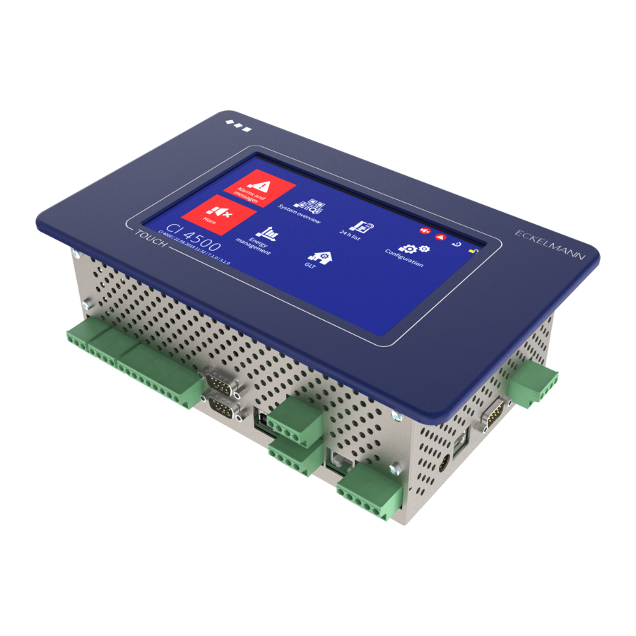
CI 4000 series system centre with touchscreen. 3.1 Application The system centres in the CI 4000 series are intended for installation in control panels. They are available in various expansion stages and their range of functions is enabled using licence codes. The system centres include the following models: CI 4000, CI 4100, CI 4400 and CI 4500;... -
Page 13: Connections In The Complete Design
The CI 4000 series does not have any direct interfaces to the old LDS1 system (VS 1000 / VS 2000 and CI 320 / CI 322)! LDS1 gateways that are connected via the COM3/MODBUS interface are required for the inclusion of LDS1 case controllers. For more details, see the “LDS1 Gateway” operating manual. - Page 14 Interfaces - bottom • 1 x COMBICON terminal 91..95 (power supply) and 1 x RJ45 port (data cable) for connecting up to max. 4 optional SIOX extension modules. • COM1 / modem port for remote access via modem using a host system or the connection of a service PC for serial direct cable connection •...
-
Page 15: Communication Interfaces
Complete range of functions: from Version V2.4.6.4082 or higher. Current information can be found at www.eckelmann.de/ldswin.. • AL 300 Operator Terminal If a system centre in the CI 4000 series is present in the E*LDS system, the AL 300 operator terminals with the following version must be used: AL 300 V5.08 or higher •... - Page 16 • UA 30 Rx series compact case controllers All control components are compatible (all versions) • VS 301x series pack controllers All control components are compatible (all versions) • WR 300 / WR 400 receiver module All versions are compatible Firmware V6.6.9 29.07.2020 16/147...
-
Page 17: System Centre Functions
4 System centre functions 4.1 Tasks and functions Functions starting with CI 4000 and higher • Central parametrisation and configuration of all E*LDS components via the CAN bus / Modbus: all E*LDS components can be operated and configured remotely via the controller (see operating manual "Basics and general security and connection instructions"). -
Page 18: Expansion Stages Of The Ci 4000 Series
Further details about the current firmware can be found in E°EDP. 4.2 Expansion stages of the CI 4000 series On the hardware side, the controller is always supplied in the complete design; on the software side, the individual expansion stages and the associated range of functions are enabled using a licence key, see chapter Menu 4-1-12 - System Upgrade. - Page 19 It is possible to upgrade at any time, for example from CI 4000 to CI 4400. Only a new licence key that can be obtained from Eckelmann AG has to be entered for this in the menu 4-1-12. The part numbers...
-
Page 20: Function Of System Centre
5 Function of System Centre 5.1 Starting Characteristics The following are distinguished for any start-up of the controller: • First start - Reset System • Restart - Restart of the controller 5.1.1 First start - Reset System Risk of loss of data and the configuration! All saved data and configurations of the system centre are irrevocably lost during deletion of the archives (operating and energy data), the alarm and message list as well as during reset to factory settings! Reset to delivery condition (factory settings), see... -
Page 21: Modbus Station Monitoring
ATTENTION The port configured in LDSWIN applies for all systems managed by LDSWIN. Therefore, configuration must be standardised here! Ports other than port 5000 should only be used in justified cases. If a connection is made via a firewall, the configured TCP/IP port must be opened for the TCP/IP service. In the event of incorrect port configuration, no communication between LDSWin and the System Centre is possible! The use of a “Well Known Port” (0-1023) can result in communication problems and ... -
Page 22: Integration Of External Controllers
The system centre is used for showing the status and for the configuration of the integrated compact case controllers M1..M50: - See Menu 2-2 for the status and display of the temperature of the individual refrigeration points. - See Menu 4-2 for configuration of name and position designation of the individual refrigeration points. Case controllers of the LDS1 system: Supported controllers: UA11 / UA111 / UA121 / UA131 / UA141 / UR141 / UA132 ... -
Page 23: Digital Inputs
• AHT cases with Danfoss controller Supported controllers: 105N462x / 105N432x / EKC 404 A • AHT cases with Wurm controller Not specified, simulated via Wurm Gateway For detailed information, see "Connection of AHT cases in the E*LDS system" operating manual. 5.4 Digital inputs ... -
Page 24: Alarm And Message Inputs
5.4.1 Alarm and message inputs Configuration Digital inputs are available for recording alarms and messages. These are disabled at the factory and must be configured in Menu 4-1-2 before use so that they operate either according to the quiescent current or the operating current principle. -
Page 25: Relay Outputs
Special input Function Toggle setpoint Detects whether the setpoints should be toggled. Then a signal for the toggle setpoint is transmitted via the CAN bus. In order to use these functions, E*LDS components must be used that also support these functions. Details can be found in the operating manual of the respective E*LDS component. -
Page 26: Multi-Function Relay Aux
The two relay outputs can be used, for example, to control a telephone dialling device. If an alarm with the priority X1 or X2 is generated by any of the E*LDS components, the assigned relay output of the corresponding priority is activated. If the output was already active, this is deactivated for approx. -
Page 27: Relay Outputs For Week Timers
Function Parameter Horn For the connection of an external audible alarm transmitter (factory setting). The contact always switches if the internal buzzer of the controller also sounds (buzzer signals an alarm). If the internal buzzer falls silent, the contact also switches to the idle state; see also chapter Alarms and messages. -
Page 28: M-Bus Interface For Consumption Data Capture
If new measuring points have been found by the scan process, these are then displayed in the list and can be configured. An overview of the supported M-bus meters can be found here: https://edp.eckelmann.de/edp/lds/_dGFHqz89xb 5.7 Alarms and messages The system centre is the collection point for alarms and messages of all E*LDS components in the system. The messages are listed in the alarm and message lists and can be called by the operator via Menu 1. -
Page 29: Explanation Of Terms For "Alarms And Messages
Priorities Function 2, 12, 22,...92 High priority alarm - entry in alarm and message lists, remote alarm is signalled, local alarm is signalled (horn), triggering of the alarm relay PRIO2, e.g. for faults that Customer Service can rectify on the next day Low priority entry in alarm and message lists, remote alarm is signalled, local alarm is 3, 13, 23,...93 signalled (horn),... -
Page 30: Acknowledgement Of Alarms And Messages
5.7.2 Acknowledgement of alarms and messages Alarms are acknowledged by tapping the adjacent button in the alarm list; see Menu 1 - Alarms and messages. The acknowledgement is performed system-wide. This means that all alarms and messages that can be acknowledged are acknowledged in all E*LDS components. ... -
Page 31: Remote Alarm Signalling
5.7.4 Remote alarm signalling There are 15 alarm destinations (3 EASY alarm destinations and 12 extended alarm destinations; see chapter Menu 4-1-7 - Alarm Signalling) available for remote alarm signalling. These destinations can be: • A PC with the PC software LDSWin •... - Page 32 maintenance costs and efficient service assignments. Example: Procedure for configuration using the LDSWin PC software Specify alarm destinations The refrigeration pack system should notify the service centre and the building control system should notify the caretaker. Specify the priorities and priority groups and assign them to the alarm destinations Refrigeration pack system: Priorities 0..9Entire installation / building control systems: Priorities 10..99 Set the priorities in the components accordingly The meaning of the priorities X1 and X2 in combination with the alarm relay must be observed, see chapter...
-
Page 33: Automatic Transmission Of Alarms Via Pushover
5.7.5 Automatic transmission of alarms via Pushover CI 4400 or higher The controller provides the possibility to automatically forward alarms and messages in plain text from the E*LDS system via the "Pushover" message service (Menu 4-1-7). A user account must be created at "Pushover"... -
Page 34: Service Mode
Risk of the failure of alarm messages via SMS and thus no alarm signalling in the event of problems! It cannot be ensured that the SMS is delivered securely and promptly to the recipient, therefore transmission of SMS messages should not be configured as the only alarm path! It is also possible that a network operator or mobile telephone service provider can change its dial-up number or its dial-up procedure from time to time, thus generating significant additional costs. -
Page 35: Alarm Suppression During Manual Shutdown Of Case Controllers
VS 3010 / VS 3010 BS / VS 3010 CT / VS 3010 WP / FS 3010 / VS 300 / VS 3010 C / VS 3015 C / VS 3015 CT System centre of the CI 4000 series 1 system centre and 1 integrated LAN gateway AL 300 operator terminal 112 .. -
Page 36: Energy Management
5.8 Energy management If the digital inputs of the system centre and/or those of any of its SIOX extension modules for energy management are configured as S0 measuring points (Menu 4-1-6) or M-bus measuring points are used (Menu 4-1-6), energy consumption, capacity, water or gas consumption etc. can be recorded. During evaluation of the tariff signal provided by the power company, the work performed can be recorded, evaluated and displayed separately according to normal tariff and peak tariff. - Page 37 actions can occur for a time interval. Therefore, a correct maximum shed load should be set for each load shedding stage used to guarantee optimum operation of the LSM. Minimum operating time A minimum operating time can be configured using this parameter. The minimum operating time specifies the time that a stage must at least be active before it is permitted to be shed again.
-
Page 38: Eu Archives (Haccp)
Operating input (optional) A digital input for signalling the operating state of the associated consumer can be used and configured for each load shedding stage. The operating input communicates the current operating status (ON/OFF) of the consumer of the respective load shedding stage to the LSM. With appropriate use of this input, the load optimisation can be significantly improved as the loading and unloading of capacity stages can be optimised by the LSM. -
Page 39: 24H List
In this way, it is also possible to view the temperature archives for up to one year in the past without the LDSWin PC software. For temperature archives further in the past that should be shown, the temperature archives must be called cyclically and saved on a PC using the LDSWin PC software. -
Page 40: System Centre Installation And Start-Up
If the device is used in any way not specified by Eckelmann AG, the protection supported by the device can be compromised! ... -
Page 41: Dip Switches
(1): Front panel (2): Rubber seal (3): 4 x stud bolt M3 x 10 mm (4): Control panel with mounting cut-out (5): 4 x drilled hole 4 mm (6): 1 x mounting frame (part number KGLRAHMEN2, only required for variant B) (7): 4 x M3: Washer / spring washer / nut ... -
Page 42: Din Rail Mounting - Siox Extension Module
• WDOG: OFF - MUST always be set to OFF • BOOT: OFF - MUST always be set to OFF 6.2 DIN rail mounting - SIOX Extension Module SIOX Extension Module: without manual control switch / with manual control switch A maximum of 4 SIOX (Serial IOExtension) extension modules can be connected to the system centre. Each SIOX module extends the system centre by an additional 12 digital inputs and 8 relay outputs. -
Page 43: Siox - Configuration Of The Jumpers
For further information, see chapters Terminal assignment of the SIOX interfaces SIOX - Terminal assignment of the interfaces. Danger of destruction of components! SIOX extension modules may only be connected to each other or the controller when no voltage is present! In the event of an Ethernet network cable with PoE (Power over Ethernet) being used instead of the SIOX data cable (RJ45) damage can occur to participating network devices! SIOX power supply cables... - Page 44 Special case: Acquisition of 24 V DC meter pulses (S0 interface)! Conditions: 1. GND of 24 V DC must be applied at the terminal level (A2 .. L2)! 2. For counting S0 pulses, these must be at least 95 ms apart from each other. Faster pulse sequences will not be detected; the pulse width must be at least 30 ms.
-
Page 45: Siox - Connection Of Energy, Gas, Water And Event Meters
Function Currently has no function Currently has no function Not jumpered = factory settings (open): The position of a manual control switch acts directly on the associated relay (ON/OFF/AUTOMATIC): the relays can be overridden manually. Jumpered: For special functions, the position of a manual control switch has no effects on the associated relay: only the controller can switch the relay. -
Page 46: Calculation Of Consumption / Power From Meter Values
6.2.3.1 Calculation of consumption / power from meter values Settings on the controller For the calculation of consumption and power using meter values of energy and quantity meters, the meter constant and transformer constant in the controller must be set in Menu 4-1-6. A: Meter constant The meter constant is used for determining the energy quantity (consumption). The number ... -
Page 47: Siox Manual / Automatic Mode Selection
Unit: none e.g. transformer with conversion ratio of 100:5 The transformer constant must only be considered in the controller if the meter at the pulse output does not take account of the transformer constant! If the transformer constant has already been taken into account for the pulse output of the meter, a 1 must be entered for this in the controller. -
Page 48: Siox - Status Leds
The following switch positions are possible: • A: Automatic ON (default switch position) If any switch is in the A position, the controller registers the logical AUTOMATIC OPERATION state: The connected equipment is controlled as the software envisages (normal operation). • O: Manual OFF If any switch is in the 0 position, the controller registers the logical MANUAL OPERATION OFF state: The connected equipment is not controlled - even if the software envisages this , e.g. -
Page 49: Can Bus - Connection Of E*Lds Components
Function Colour LED Description Digital LED1 On: Digital input is activated inputs ATTENTION DANGER TO LIFE: External voltage can be present at these terminals! LED12 Relay green LED1 On: Relay is activated outputs ATTENTION DANGER TO LIFE: External voltage can be present at these terminals! LED8 Communicatio green... - Page 50 Setting the CAN bus address is not required as the CAN bus addresses 111 and 127 are permanently assigned to the system centre. Example of possible CAN bus constellations: For details about the connection, see chapter Terminal assignment of the CAN bus terminals. ...
-
Page 51: Modbus Connection Of Case Controllers
6.4 Modbus connection of case controllers Only CI 4100 or higher: The "COM3/MODBUS" connection is used for the integration of RS485 controllers in the E*LDS-System. The following controllers are supported: • UA 30 RC / UA 30 RS compact case controllers; for details, see chapter Integration of case controllers of the E*LDS system •... -
Page 52: Status Leds Of The M-Bus Gateway
The following M-bus gateways are available: • for max. 20 M-bus meters • for max. 60 M-bus meters The 3 terminal pairs M+/M- are used to distinguish between the M-bus cables. However the polarity for M-bus installations is completely unimportant! A power supply is required for both M-bus gateways. For details about the part numbers, see chapter .Accessories for system centre v6.0. -
Page 53: Modem Hardware Reset
After installation of the system centre and the modem, as well as the configuration of the automatic transmission of alarms, the message path should be checked regularly by triggering test alarms (Menu 4-1-7 - Other). For trouble-free operation, only modems approved by Eckelmann AG are permitted to be used for operation at the system centre: •... -
Page 54: Sms Text Message Transmission Via A Gsm Modem
The function of the multifunction relay AUX must be set to modem reset. If this setting has been selected, the system centre checks the availability of the modem and initiates a modem hardware reset automatically as required. If a modem hardware reset is needed, the system centre now switches off the modem for a short time (approx. - Page 55 Using touch screen Input directly on the device; for details see Operation and access to the system centre. Using serial connection to the USB slave port, a more detailed description for "PC direct connection via USB to the system centre"...
-
Page 56: Status Leds Ethernet
For details about VNC, see chapter Remote operation of the system centre using VNC (Virtual Network Computing). 6.8.1 Status LEDs Ethernet Function Colour Description ▪ ON: Ethernet connection present Ethernet green LED 1 ▪ Flashing: data transfer ▪ ON: 100 MBit/s yellow LED 2 ▪... -
Page 57: Special Function For Commissioning
No battery replacement for the controller by the user is envisaged as the battery service life is designed for greater than 10 years. If the "battery voltage" message is displayed, the controller must be sent to Eckelmann AG to guarantee correct replacement of the battery. Opening the device is not authorised, see chapter... -
Page 58: Performing Firmware Update
• The new firmware must be available; this is usually provided as a compressed ZIP archive, e.g. at https:// edp.eckelmann.de/edp/lds/_a8DwY2ZwdN. • The ZIP- archive (it contains the directory "CI4000") must be unpacked using a PC into the root directory of a USB stick (1 GB .. -
Page 59: System Centre And Siox Connection / Terminal Assignment
7 System centre and SIOX connection / terminal assignment • System centre terminal diagram • SIOX extension module terminal diagram 7.1 System centre terminal diagram Warning about dangerous electrical voltage! In order to guarantee reverse polarity protection, only coded mating connectors may be used on the control component connections. The following figure shows the system centre in its complete design: The detailed description of the connection and terminal assignments of the system centre and its components is shown on the following pages. -
Page 60: Terminal Assignment Of The 230 V Ac Digital Inputs
Terminal No. Function N, L, PE 230 V AC power supply (SUPPLY): Neutral conductor, phase 230 V AC, PE (ground conductor) PE on grounding screw M4 PE (ground conductor) with ring cable lug on device cage Warning about dangerous electrical voltage! Instruction for protective earthing: The ground conductor must also be connected to the grounding screw M4 on the rear side of the device cage using a ring cable lug. -
Page 61: Terminal Assignment Of The 230 V Relay Outputs
Terminal No. Function A1, A2 Digital input 1 (IN1), 230 V AC (floating) B1, B2 Digital input 2 (IN2), 230 V AC (floating) For details about the configuration, see chapter .Digital Inputs v6.0. 7.1.3 Terminal assignment of the 230 V relay outputs The two relay outputs PRIO1/PRIO2 can be used for sending alarms with these priorities. -
Page 62: Terminal Assignment Of The Can Bus Terminals
Terminal No. Function 15 (common) Multifunction relay AUX: can be configured using Menu 4-1-7 as 16 (normally closed contact) • horn 18 (normally open contact) • additional alarm relay with the priority PrioX3, PrioX4, PrioX5, PrioX6, PrioX7, PrioX8 or PrioX9 • Modem hardware reset, • for switching the modem to the DDC (T-connector required) 25 (common) Alarm relay PRIO2: Alarm for messages with priority 2 (PRIO.2) 26 (closed in the alarm state) - Page 63 Connection to the CAN bus, shown here using the first CAN bus segment (CAN1) as example. This also applies for the second CAN bus segment (CAN2). CAN1 - First CAN bus segment CAN2 - Second CAN bus segment Standard Only CI 5500: Repeate function Terminal No.
-
Page 64: Terminal Assignment Of The Siox Interfaces
PoE (Power over Ethernet) being used instead of the SIOX data cable (RJ45) damage can occur to participating network devices! Only components approved by Eckelmann AG may be connected to the SIOX extension bus (terminals SIOX OUT / SIOX IN or terminals 91..95)! Terminal No. -
Page 65: Terminal Assignment Of Communication Interfaces
Warning about dangerous electrical voltage! If mains voltage is connected to the Modbus terminals, this will result in the destruction of all components connected to the Modbus! Modbus supply lines must be shielded (cable type: J-Y(ST)Y 2x2x0.8 mm )! As a general rule, care should be taken to ensure that signal cables and cables carrying mains voltage are routed in separate cable channels... - Page 66 Interfaces at the bottom on the device Interface Designation Type Function CAN bus CAN1 / CAN2 Connection of the system centre to COMBICON terminal • the first CAN bus segment via CAN1, blocks • the second CAN bus segment via CAN2 (CAN2 only for CI 4500 or higher). For details, see chapter Terminal assignment of the CAN bus terminals.
-
Page 67: Siox Extension Module Terminal Diagram
ETHERNET/ RJ45 female Ethernet / LAN interface (CI 4400 or higher) for the connection of the PC software connector LDSWin For details about dependencies in the expansion stages, see chapter Communication interfaces. 7.2 SIOX extension module terminal diagram Warning about dangerous electrical voltage! In order to guarantee reverse polarity protection, only coded mating connectors may be used on the control component connections. The following figure shows a SIOX (Serial IO Extension) extension module with switches: The description of the connection and terminal assignments for the digital inputs, the relay outputs and the SIOX interface is provided on the following pages. - Page 68 Note: The digital inputs of the SIOX extension module in the example are used / configured as follows: • The first 8 digital inputs A2..H2 have been configured for 230 V AC using jumpers. • Ideally, A2..H2 are connected to N. •...
-
Page 69: Siox - Terminal Assignment Of The 230 V Ac Relay Outputs
Digital input Terminal No. Function Without switch * With switch * J1, J2 68, 69 K1, K2 70, 71 L1, L2 72, 73 * COMBICON terminal blocks of the extension modules • Without switch - Digital inputs: 2-position COMBICON terminal blocks 12 x ... - Page 70 In order to fuse the supply line and relay outputs, a circuit breaker with the following characteristics must be used for each relay output: • Rated current for 230 V AC: 6(3) a • Tripping characteristic (typical): B Note: In the example here, the first relay output of the SIOX extension module is used as a defrost timer for a case controller.
-
Page 71: Siox - Terminal Assignment Of The Interfaces
Maximum 4 extension modules can be connected to the system centre. Only components approved by Eckelmann AG may be connected to the SIOX extension bus (terminals SIOX OUT / SIOX IN or terminals 91..95)! The total length of the cabling for the SIOX cables and the SIOX data cables is maximum 30 m in each case! Terminal No. - Page 72 Terminal No. Function SIOX 24 V DC - no function WARNING: These terminals must not be used to supply any external consumers (e.g. energy meters)! Practical tip: A separate power supply (part number KGLNT23024) must be used for the supply of external consumers; see chapter .Accessories for system centre v6.0 Ground of 24 V DC +24 V DC...
-
Page 73: Operation And Access To The System Centre
8 Operation and access to the system centre The following possibilities for the operation of and access to the system centre are available: Access via Operation via Type of connection Touch screen Local Machine room Direct input using the touch screen of the device. - Page 74 Access via Operation via Type of connection Remote Remote access via modem at the LDSWin Refrigerated display case COM1 interface manufacturer & Service, store operator, supply chains, Via Internet and LAN connection remote maintenance centres & emergency services Via Internet and LAN connection using VNC;...
- Page 75 ATTENTION Violation of data protection! The Combi-Gateway is not equipped with any security mechanisms for the encryption of communication via the LAN interface. For this reason, connections should only be established in secure networks. For communication via public or insecure networks, additional security components (e.g.
-
Page 76: Menus Of The System Centre
9 Menus of the system centre 9.1 On-site at the device 9.1.1 Layout of the touch screen The touch display of the system centre is divided into various fields for different functions, for example here the main menu: Status bar and quick info: Menu numbers and titles of the displayed menus or entry screens. The Info/ Help button and the two quick access buttons for acknowledgement of the alarms and for calling up the alarm list (in red here) and the list of unloaded / failed case controllers (in yellow here) can also be found here. -
Page 77: Status Bar And Quick Info
9.1.1.1 Status bar and quick info Button No. Function Home - display main menu, only visible in submenus Back - one menu level back, only visible in submenus Exception: If the diagram of the 24h list is open, this button jumps back to the main menu! If you would only like to return to the table form view of the 24h list, the button at the bottom left in the navigation area must be tapped. - Page 78 Button No. Function Create new entry (e.g. a new run time or week timer). Open the entry screen or symbol for editing. Parameters are displayed or can be edited, configured or changed and entries can be added or deleted. Among other things, this symbol is also visible in lists to obtain detailed information. Open remote control of components, see chapter Remote control of E*LDS components (terminal mode).
- Page 79 2. Numeric keypad for the entry of numbers with plausibility check (left). If the entry field has a red background (right), the input value is not plausible or not permitted and must be corrected. Depending on the parameter, characters are partially greyed out to prevent inadmissible input. 3.
-
Page 80: Navigation And Other
9.1.1.3 Navigation and other Button No. Function Home - display main menu, only visible in submenus Back - one menu level back, only visible in submenus Exception: If the diagram of the 24h list is open, this button jumps back to the main menu! If you would only like to return to the table form view of the 24h list, the button at the bottom left in the navigation area must be tapped. - Page 81 Symbols Description If the lock is closed (white), nobody is logged in (system centre locked down); inputs or changes to the configuration of E*LDS components are not possible. Login: Tap on symbol and enter user details / password. If the lock is open (yellow), a user is logged in (system centre is unlocked); inputs or changes to the configuration of the system centre or to E*LDS components can be made.
-
Page 82: Service Mode - Suppression Of Remote Alarm Signalling
9.1.2.1 Service mode - suppression of remote alarm signalling After the login, another symbol is shown automatically on the left next to the padlock; this symbol is used in the service mode for suppression of the remote alarm signalling. Symbol Description This button is not displayed until after successful login to the device. -
Page 83: Operation In Terminal Mode
The remote control (terminal mode) screen looks like the following: "Terminal Display" (4 lines of 20 characters) for display of the menu of the E*LDS component (the arrow buttons must be used for paging; "swiping" cannot be done in this screen!). A menu item, e.g. - Page 84 be available than can be shown on the display. In this case, these values can be displayed by scrolling. If an operating screen contains several pages, these can be paged through. If it is possible to scroll or page in a menu or an operating screen, this is indicated by direction arrows on the right in the display.
-
Page 85: Specification Of The Numbering Of Menus And Entry Screens
Tip: The parameters of the case controller for name, position and priority can be very comfortably configured using the configuration screen in the respective submenu of the E*LDS component (e.g. Menu 4-2, 4-3 or 4-4). Delete input text The MODE button and - must be tapped simultaneously to delete the complete text line. A character is deleted using the button combination MODE and , . -
Page 86: Overview Of The Menu Tree
→ → → * Login to the system centre is required, see chapter Login to the system centre (unlocking). In this operating manual, all references to menus or entry screens and their functionalities and/or the parameters to be set there use the type of numbering presented here. 9.1.5 Overview of the menu tree ... - Page 87 3 - Special inputs Special inputs 4-1-3 - shunt lock - emergency power operation - sprinkler alarm - store lighting - setpoint toggle 4 - Week timers Week timers 4-1-4 5 - Interfaces Interfaces 4-1-5 - COM1/Modem - COM2 - COM3/MODBUS - COM4 - Ethernet - USB 6 - Measuring points...
-
Page 88: Main Menu
9.1.5.1 Main menu Brief description of the buttons Main menu 1 Alarms and messages List of the current alarms and messages 2 System overview Overview and monitoring of the installation and all E*LDS components 3 24h list Display of the 24h list(s) 4 Configuration Configuration of the system 5 Horn... - Page 89 This symbol must be confirmed for the acknowledgement of the rectified alarms. Acknowledged alarms are automatically moved into the message list, forming the history of the alarms that have occurred in the installation. The screen contains the following information Incoming: Date and time of alarms and messages as they occurred (receive time stamp). Outgoing - in the alarm list: If any red alarm symbol can be seen in this column, this means that alarms with the priority 1..9 are still pending, the faults have not yet been rectified and these alarms cannot be acknowledged! On the other hand, if there is a date and time in this column, the problems or causes of the alarm have been rectified and the alarm has gone and can be acknowledged using the acknowledge button in the right area.
- Page 90 Outgoing - in the message list: If any red alarm symbol can be seen in this column, this means that alarms with the priority 1..9 are still pending, the fault has not yet been rectified. Alarms and messages with priority 1..99 can only be acknowledged in the alarm list. If any yellow symbol can be seen in this column, this means these are messages with the priority 9 and the messages do not yet have a send time stamp.
- Page 91 Brief description of the buttons 2 - Overview and monitoring of the system (all menus are "read-only!") 1 Node overview Node overview of all the E*LDS components in the system. 2 Case controllers Overview of all case controllers 3 Pack controllers Overview of all pack controllers 4 Receiver module wireless sensors Overview of all receiver modules and wireless sensors 5 Other LDS components...
- Page 92 Diverse statuses and operating states are also displayed. Symbol Meaning The status of the connection (communication) with the node is OK The status of the connection (communication) with the node is unknown The node has failed The node has been unloaded The status of the node is OK The node has alarm status Remote control using terminal mode...
- Page 93 Diverse statuses and operating states are also displayed. Symbol Meaning The status of the connection (communication) with the node is OK The status of the connection (communication) with the node is unknown The node has failed The node has been unloaded The status of the node is OK The node has alarm status Remote control using terminal mode...
- Page 94 Symbol Meaning The status of the connection (communication) with the node is OK The status of the connection (communication) with the node is unknown The node has failed The node has been unloaded The status of the node is OK The node has alarm status Remote control using terminal mode Tapping the Remote Control button opens the terminal mode screen.
- Page 95 Diverse statuses and operating states are also displayed. Symbol Meaning The status of the connection (communication) with the node is OK The status of the connection (communication) with the node is unknown The node has failed The node has been unloaded The status of the node is OK The node has alarm status Remote control using terminal mode...
- Page 96 The screen contains the following parameters: Signal inputs Message text Message text of the signal input (digital input) Priority XX Priority of the signal / alarm input Delay time [Min.] XX Delay time of the signal / alarm in minutes Quiescent current (low-active) X Alarm is signalled if - quiescent current = Yes: (signal voltage not present, low-active)
- Page 97 Special inputs Shunt lock Predefined designation of the special input (digital input) Priority XX Priority of the signal / alarm input Delay time [sec.] XX Delay time of the signal / alarm in seconds Quiescent current (low-active) X Alarm is signalled if - quiescent current = Yes: (signal voltage not present low-active) - quiescent current = No: (signal voltage is present high-active) Input X Connection of the input ...
- Page 98 QR code with specification of the hyperlink where further information about the use of Open Source software components (Licence Reports) is described in detail for the present product: Link to E°EDP of Eckelmann AG: https://edp.eckelmann.de/edp/lds/ _V0brLLadsi 10 Menu 2-10 - Log Using this button, the entries for the installation stored with the LDSWin PC software (e.g. last ...
- Page 99 The 24h display is divided into three time ranges of 8 hours each that can be displayed alternating between 0:00 to 7:00, 8:00 to 15:00 and 16:00 to 23:00 using the buttons on the bottom left edge of the screen. The 8:00 to 15:00 time range is the default while the other time ranges are zoomed out.
- Page 100 4 - Configuration System 4 Receiver module wireless sensors Configuration of all receiver modules and wireless sensors 5 General information General system information 6 User Configuration of the user management 7 Log Log of the system centre or the installation 8 Language Settings of the language displayed in the E*LDS system 9 Other LDS components...
- Page 101 4 - Configuration System Centre 6 Measuring points Configuration of the measuring points 7 Alarm is signalled Configuration of the alarm signalling 8 Date / time Setting of date and time 9 Firmware Update Update of the firmware and the bootloader 10 System Information System information 11 System Reset...
- Page 102 Note: GLT = Building Control System and DDC = Digital Direct Control Menu 4-1-2 - Signal Inputs This button is used to call up the list of the digital alarm and signal inputs of the system centre. All important parameters and the status of the inputs are displayed there. Alarm and signal inputs can be added using the "New entry" button. Already added digital inputs can be selected and configured using the corresponding screen or deleted again.
- Page 103 Menu 4-1-3 - Special Inputs The special inputs of the system centre are called up using this button. See chapter Special inputs for details. All important parameters and the status of the inputs are displayed there. The required special inputs can be selected and configured using the corresponding screen. Special inputs are permanently predefined in the system centre and cannot be deleted or added; it is only possible to delete their configuration. ...
- Page 104 SIOX3 3. extension module, inputs 1 .. 12 SIOX4 4. extension module, inputs 1 .. 12 DDC1 1. GLT DDC module 1 DDC2 2. GLT DDC module 2 DDC3 3. GLT DDC module 3 DDC4 4. GLT DDC module 4 Note: GLT = building control and. DDC = Digital Direct Control Only those SIOX modules and GLT PLC modules are provided for selection that have been configured accordingly in screen 4-1-1! A description of the functions can be found in chapter Digital inputs.
- Page 105 Designations of the supported modules / outputs: SIOX1 1st extension module, outputs 1 .. 8 SIOX2 2nd extension module, outputs 1 .. 8 SIOX3 3rd extension module, outputs 1 .. 8 SIOX4 4th extension module, outputs 1 .. 8 DDC1 1st GLT DDC module 1 DDC2 2nd GLT DDC module 2 DDC3 3rd GLT DDC module 3 DDC4 4th GLT DDC module 4 ...
- Page 106 The screen contains the following parameters: Interface - CAN2 Input Default Setting of the operating mode for the 2nd CAN bus interface Repeater CI 4500: no function or as CAN bus repeater for details, see chapter CAN bus - Connection of E*LDS Components Interface COM1/Modem - all CI 4x00 The COM1 interface is configured in this screen. The COM1 interface can be used as modem or as ...
- Page 107 Number of stop bits Handshake Handshake available none * More about the Modbus RTU interface see https://edp.eckelmann.de/edp/lds/_dH7IGZeEJK. Interface Ethernet - only CI 4400 or higher The Ethernet interface for the connection in a LAN is configured in this screen. This interface is used for the data exchange and communication with LDSWin. An Ethernet crossover patch cable CAT5 is needed for a local connection between system centre and...
- Page 108 Interface - Ethernet Input Default Alternative DNS server Input of the alternative DNS server Numbers An error message is output if the changed values are not applied when saving! Then the values actually used by the system centre are displayed again on the entry screen. Interface USB - all CI 4x00 An update (e.g.
- Page 109 The screen contains the following parameters: 4-1-6 - Measuring points Input Default Name Name of the measuring point max. 19 characters Meter type XX Selection of the meter type. Power After selection of the meter type, this is displayed Water graphically, see legend.
- Page 110 Primary address Only for M-bus meters: the M-bus has an address range of 1..255. The M-bus meters are identified via the primary address. The primary address must be configured in the meter. Therefore, a unique address must be allocated during first start-up that may only be used once on the M-bus.
- Page 111 DDC3 3rd GLT DDC module 3 DDC4 4th GLT DDC module 4 Note: GLT = Building Control and DDC = Digital Direct Control Only those SIOX modules and GLT PLC modules are provided for selection that have been configured accordingly in screen 4-1-1! A description of the functions can be found in chapter Digital Inputs.
- Page 112 Pushover alarms Pushover alarms Input Default Pushover activated The check mark must be set for activation of the transmission of alarms via Pushover Selection of the priorities The alarm priorities for which transmission of alarms via Pushover should be performed can be selected in the priority matrix.
- Page 113 LDSWin alarm signalling Entry Default Time range Messages are Never, Within, Outside, Always Never never, within, outside or always transmitted in the time range. LDSWin It is defined using this entry screen where the alarm is signalled in the event of a fault or which remote station with the LDSWin PC software is contacted.
- Page 114 The screen contains the following parameters: LDSWin alarm signalling Entry Default LDSWin Description Description of the remote station of max. 19 characters Fault reporting service LDSWin, e.g. fault reporting service Telephone number Telephone number of the remote station Priority Priority Alternative destination of Alternative destination of destination 0, 1, 2, 1 + 2...
- Page 115 The screen contains the following parameters: Alarm signalling time ranges Entry Default Start Week timer start 00:00..23:59 08:00 Week timer end 00:00..23:59 16:00 XXXXXXXXX Weekdays and groups of days Mon-Fri Mon - Fri Mon-Sat Mon-Sun Sat-Sun Mon, Tue, Wed, Thu, Fri, Sat, Sun ...
- Page 116 Alarm signalling other Entry Default AUX relay Function XXX The multi-function relay AUX must be set to Horn, Horn PRIOX3, .. or PRIOX9 so that it can be used as alarm relay PrioX3, alarm relay! PrioX4, PrioX5, PrioX6, For details about the configuration, chapter PrioX7, PrioX8, PrioX9 Multi-function relay AUX, page 30.
- Page 117 Any change of the time zone or the date results in inconsistencies in the data archiving as the assignment of the recorded data (EU archives, temperatures, alarms etc.) to their actual time stamps is lost as a result! Changes can only be made by authorised personnel and are only possible with login as "Master".
- Page 118 Firmware Update Input Defa 3.Now perform If the above check box has been checked and the "Now perform update and restart" button has been update and restart tapped, the update is "prepared" in the background. This process can take a few seconds (approx. 5 seconds).Then the system centre performs a restart and the new firmware is loaded.
- Page 119 Expansion stages of the CI 4000 series and new functions are enabled using a licence key that can be requested from Eckelmann AG. The part numbers of the individual expansion stages are listed in chapter Order numbers and accessories of System Centre.
- Page 120 The assigned CAN bus address, diverse statuses and operating statuses are also displayed. Symbol Meaning The status of the connection (communication) with the node is OK The status of the connection (communication) with the node is unknown The node has failed The node has been unloaded The status of the node is OK The node has alarm status...
- Page 121 3 Menu 4-3 - Pack controllers The submenu for configuration of the pack controllers is called using this button. All important parameters and the status of the pack controllers are displayed there. Pack controllers can be added using the "New entry" button. Already added pack controllers can be selected and configured using the corresponding screen.
- Page 122 Remote control using terminal mode The terminal mode screen is opened using the Remote Control button. All parameters of the pack controller can be configured in the terminal mode. For more information, see chapter Remote control of E*LDS components (terminal mode).
- Page 123 QR code with specification of the hyperlink where further information about the use of Open Source software components (Licence Reports) is described in detail for the present product: Link to E°EDP of Eckelmann AG: https://edp.eckelmann.de/edp/lds/ _V0brLLadsi 6 Menu 4-6 - Users The screen for user management of the system centre is called up using this button. All users ...
- Page 124 User Admin New password Repeat new password The requirements above must be observed! Master New password Repeat new password The requirements above must be observed! Service New password Repeat new password The requirements above must be observed! It is recommended to choose a password that meets certain minimum requirements for a good password.
- Page 125 Symbol Meaning The status of the connection (communication) with the node is OK The status of the connection (communication) with the node is unknown The node has failed The node has been unloaded The status of the node is OK The node has alarm status The screen contains the following parameters: Configuration Case Controllers...
- Page 126 However, for each new alarm, the audible signalling units of the alarm centre are activated and the horn button colour changes to red. Pressing the button switches off the audible signalling units again and the button changes colour to white again. Switching off the audible alarm signalling units does not acknowledge alarms! The acknowledgement of alarms can only be performed using the acknowledge button in the alarm list (Menu 1), see chapter Menü...
-
Page 127: Remote
Individual time periods (days, months, years) can be changed between by pressing the left/right buttons. Note: The "year" time period cumulates the daily consumptions to the month consumption. 2 Menu 6-2 - Load Profile The submenu for display of the load profile of the individual meter types is called up using this button. Legend for the meter symbols used: Energy, water, gas, heat, oil and event Every line entry in the screen contains the following parameters: Type and name of the meter, its position designation, the meter and transformer constants and the unit of... -
Page 128: Remote Operation Of The System Centre Using Vnc (Virtual Network Computing)
The interface is configured using Menu 4-1-5. For more details, see chapter Terminal assignment of communication interfaces. 9.2.1 Remote operation of the system centre using VNC (Virtual Network Computing) The system centre can be remotely operated using VNC with, for example, the UltraVNC Viewer (htttp:// www.uvnc.com/). - Page 129 After establishment of the VNC connection, it is possible to operate the system centre using the PC keyboard and mouse. Firmware V6.6.9 29.07.2020 129/147...
- Page 130 If the system centre is not operated for a longer time, the screen saver for protection of the display is activated. If a VNC connection exists, the screen saver is deactivated with the first mouse click. Firmware V6.6.9 29.07.2020 130/147...
-
Page 131: Decommissioning And Disposal
Our scope of delivery is a component that is intended exclusively for further processing. As a consequence of this fact, Eckelmann AG does not take any measures for the taking back or municipal recycling of this product as it is not supplied directly to the free market. -
Page 132: System Centre Alarms And Messages
11 System centre alarms and messages The following list contains all alarm and message texts with error number that are signalled by the system centre in Menu 1 (Alarms and messages). There is a brief explanation of the possible cause and suggestions for remedy / elimination of the error for each of these alarms and for each message. - Page 133 Error in alarm signalling module Please contact Customer Service internal error 42 4E20 internal error 42 4E21 internal error 42 4E22 internal error 42 4E23 internal error 42 4E24 internal error 42 4E25 internal error 42 4E26 internal error 42 4E27 internal error 42 4E28 internal error 42 4E29 internal error 42 4E2A...
- Page 134 xxxxxxxxxxxxxxxxx The limit value of a totaliser has been exceeded The name of the totaliser (freely editable) whose parametrised limit value has been exceeded is in the system message Backup Alarm Config Alarm configuration has been restored from Please contact Customer Service the backup 0 ...
- Page 135 0 Pushover data error The configuration data for Pushover have Please contact Customer Service errors. Pushover file error Configuration for Pushover could not be Please contact Customer Service loaded Pushover error: x An error with the error number x has occurred Please contact Customer Service during the transmission of messages and alarms via Pushover.
- Page 136 Time adjustment The time in the system centre has been adjusted. Date adjustment The date in the system centre has been adjusted. Verst. System time The date and time in the system centre have been adjusted. Verst. Time zone The time zone of the system centre has been adjusted.
- Page 137 Computer fault or The system centre cannot communicate with Check: Computer fault Mxx or the stated components: • power supply and connection of Computer fault Wxx • E*LDS component on the CAN bus • Modbus component Mxx E*LDS component on the CAN •...
- Page 138 xxxxxxxxxxxxxxxxx Text is freely editable for Eliminate fault of the external alarm message or alarm input on the system centre e.g. input: int.E/1 (digital input IN1, terminal A1/A2) message or alarm input on the SIOX extension module e.g. input: SIOX2/5 (2nd SIOX module / digital input 5, terminal E1/E2) Emergency power supply Special input emergency power supply has...
- Page 139 LP too low Mxx* Lower limit value t at compressor Mxx Check compressor Mxx undercut External alarm Mxx* Error message of component Mxx Check component Mxx Wurm node error messages Sensor fault Wxx* • Check connection cable Sensor fault on component Wxx .
-
Page 140: Specifications Of System Centre And Siox
12 Specifications of System Centre and SIOX For safety reasons and to guarantee important functions (e.g. alarm forwarding to a service centre via modem) only accessories approved by Eckelmann AG (see chapter Zubehör für Systemzentrale) are permitted to be used with the system centre. -
Page 141: Mechanical Data
CE conformity according to Official Journal of the EU L96, 29/03/2014, pages 357-374 • EMC Directive 2014/30/EU; (see Official Journal of the EU L96, 29/03/2014, pages 79-106 https://edp.eckelmann.de/ • RoHS Directive 2011/65/EU; edp/lds/_aftpgg7so5) Official Journal of the EU L174, 01/07/2011, pages 88-11 ... -
Page 142: Dimensions
12.2.1 Dimensions 12.2.2 Control panel cut-out Variant A: Technically most attractive solution with somewhat complex manufacture of the panel cut-out and the 4 x 4 mm holes Variant B: The rectangular panel cut-out can be realised quickly with a jigsaw, e.g. during commissioning / service;... - Page 143 Firmware V6.6.9 29.07.2020 143/147...
-
Page 144: Mounting Frame For Control Panel Installation
12.2.3 Mounting frame for control panel installation (1): mounting frame, part number: KGLRAHMEN2 Firmware V6.6.9 29.07.2020 144/147... -
Page 145: Siox Extension Module
12.2.4 SIOX extension module Without manual control switches With manual control switches 12.3 Information on open source software Information for Open Source software is shown in Menu 4-5 - General Information v6.0 or at https:// edp.eckelmann.de/edp/lds/_V0brLLadsi Firmware V6.6.9 29.07.2020 145/147... -
Page 146: Order Numbers And Accessories Of System Centre
SIOX without manual control switch LISIOX0011 SIOX with manual control switch (Auto/Off/Manual) LISIOX0012 For details, see chapter Expansion stages of the CI 4000 series 13.2 Accessories for system centre Accessory part Description Part number Mounting frame Mounting frame for attachment in switch cabinet... - Page 147 Accessory part Description Part number SUB-Min-D connector 9 pole SUB-Min-D connector (male) with screw terminals for STSUBCON9M Modbus connection Package for inclusion - For AHT chest freezers with Danfoss SLV controllers KGLAHTAD01 of AHT chest freezers - For AHT chest freezers with Wurm controllers KGLAHTAD02 - For AHT chest freezers with Danfoss SLV and Wurm KGLAHTAD03...
Need help?
Do you have a question about the CI 4000 Series and is the answer not in the manual?
Questions and answers