
Related Manuals for Daikin FTX36WVJU9


Summary of Contents for Daikin FTX36WVJU9
- Page 1 DAIKIN ROOM AIR CONDITIONER INSTALLATION MANUAL R410A Split Series Installation manual Manuel d’installation Manual de instalación MODELS FTX30WVJU9 FTX36WVJU9...
-
Page 2: Table Of Contents
Contents Safety Considerations ........1 Refrigerant Piping Work ........9 1. Flaring the pipe end ............. 9 Accessories ............3 2. Refrigerant piping............9 Choosing an Installation Site ......3 Installation Tips ..........10 1. Indoor unit ..............3 1. Removing and installing the front panel..... 10 2. - Page 3 • Indoor units are for indoor installation only. Outdoor units specified by Daikin are used, fire or explosion may occur. can be installed either outdoors or indoors. • Do not use means to accelerate the defrosting process (if •...
-
Page 4: Accessories
Accessories Mounting plate Mounting plate Titanium apatite photocatalytic fixing screw air-purifying filter M4 × 1” (M4 × 25mm) Wireless remote Remote Remote controller controller holder controller holder fixing screw M3 × 13/16” (M3 × 20mm) Dry battery Indoor unit Screw cover AAA. -
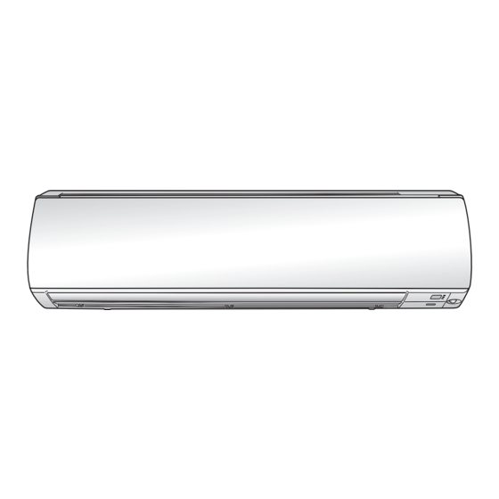
Page 5: Indoor Unit Installation Diagram
Indoor Unit Installation Diagram CAUTION • Do not hit or violently push the INTELLIGENT EYE sensor. This can lead to damage and malfunction. • Do not place large objects near the INTELLIGENT EYE sensor. Also keep heating units or humidifiers outside the sensor’s detection area. -
Page 6: Indoor Unit Installation
Indoor Unit Installation Installing the mounting plate The mounting plate should be installed on a wall which can support the weight of the indoor unit. 1)Temporarily secure the mounting plate to the wall, make sure that the plate is completely level, and mark the drilling points on the wall. - Page 7 3-2. Left-side, left-back, or left-bottom piping How to switch around the drain plug and drain hose 1) Remove the fixing screw and 3) Switch around the drain hose and drain plug. Insert drain hose securely pull out the drain hose. and fix in place with fixing screw.
-
Page 8: Wiring
Indoor Unit Installation Wiring Refer to the installation manual for the outdoor unit also. WARNING • Do not use tapped wires, extension cords, or starburst connections, as they may cause overheating, electric shock, or fire. • Do not use locally purchased electrical parts inside the product. (Do not branch the power for the drain pump, etc., from the terminal block.) Doing so may cause electric shock or fire. -
Page 9: Drain Piping
Drain piping 1) Connect the drain hose, as described on the right. • Avoid placing the end of the drain hose in a drainage location that could Make a downward slope cause bad odours or corrosive gas to flow backward into the outlet. •... -
Page 10: Refrigerant Piping Work
Refrigerant Piping Work WARNING • Do not apply mineral oil on flared part. • Prevent mineral oil from getting into the system as this would reduce the service life of the units. • Never use piping which has been used for previous installations. Only use parts which are delivered with the unit. •... -
Page 11: Installation Tips
Installation Tips Removing and installing the front panel • Removal method 1) Place your fingers in the indentations on the main unit (one each on the left and right sides), and open the front panel until it stops. 2) While pushing the left side front panel shaft outward, push up the front panel and remove it. -
Page 12: How To Set The Different Addresses
Installation Tips How to set the different addresses Pull Pull When 2 indoor units are installed in one room, the 2 wireless remote controllers can Slide Slide be set for different addresses. Change the address setting of one of the 2 units. When cutting the jumper, be careful not to damage any of the surrounding parts. -
Page 13: Trial Operation And Testing
Trial Operation and Testing Trial operation and testing • Trial operation should be carried out in either COOL or HEAT operation. 1-1. Measure the supply voltage and make sure that it is within the specified range. 1-2. In COOL operation, select the lowest programmable temperature; in HEAT operation, select the highest programmable temperature. - Page 14 The two-dimensional bar code is a manufacturing code. 3P686874-1 M21B543 (2206) HT...
Need help?
Do you have a question about the FTX36WVJU9 and is the answer not in the manual?
Questions and answers