
Related Manuals for J-Tech Digital JTD-2985


Summary of Contents for J-Tech Digital JTD-2985
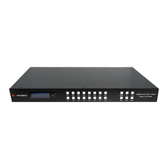
- Page 1 USER MANUAL 4K60Hz 8x8 HDMI 2.0 Matrix Switch JTD-2985 | JTECH-88B J-TECH DIGITAL INC. 9807 EMILY LANE STAFFORD, TX 77477 TEL: 1-888-610-2818 E-MAIL: SUPPORT@JTECHDIGITAL.COM...
- Page 2 Thank you for purchasing this product. For optimum performance and safety, please read these instructions carefully before connecting, operating or adjusting this product. Please keep this manual for future reference. SAFETY PRECAUTIONS Please read all instructions before attempting to unpack, install or operate this equipment and before connecting the power supply.
-
Page 3: Table Of Contents
Table of Contents 1. Introduction......................... 5 2. Applications........................ 5 3. Package Contents....................... 5 4.System Requirements....................6 5. Features........................6 6. Specifications......................6 7. Operation Controls and Functions................7 7.1 Front Panel..........................7 7.2 Rear Panel. - Page 4 8. Audio Introductions....................33 8.1 HDMI Audio......................... 33 8.2 Audio Extraction........................34 8.2.1 Analog Audio Extraction......................34 8.2.2 SPDIF Audio Extraction......................34 8.3 Audio Embedding........................ 34 8.4 ARC Audio.......................... 34 9. EDID Management....................35 10.
-
Page 5: Introduction
1. Introduction This 8x8 4k HDMI Matrix supports the transmission of video (resolutions up to 4K2K@60Hz, HDCP 2.2, HDMI2.0) and multi- channel digital audio from 8 HDMI sources to 8 HDMI outputs and 8 SPDIF Output. This matrix supports high resolution digital audio formats such as Dolby TrueHD and DTS-HD Master Audio as well as 3D video content. -
Page 6: System Requirements
4. System Requirements HDMI source equipment such as media players, game consoles or set-top boxes. • HDMI receiving equipment such as HDTV, monitors, or audio amplifiers. • The use of “Premium High-Speed HDMI” cables is highly recommended. • 5. Features HDMI 2.0 Matrix system with 8 inputs and 8 outputs •... -
Page 7: Operation Controls And Functions
Audio Input Connectors 8 x Analog audio, 3.5mm, female Audio Output Connectors 8 x Analog audio, 3.5mm, female, 8 x SPDIF Coaxial RS-232 serial port DB9, female Ethernet port (IP control) RJ45, female 1x3.5mm stereo jack IR Ext port Dimensions (WxHxD) 482.4mm x 220mm x 44mm | 18.99”... -
Page 8: Rear Panel
7.2 Rear Panel 7.3 LCD Screen Information... -
Page 9: Input / Output Channel Key Operation
7.3.1 Input / Output Channel Key Operation 7.3.2 Video Switching Operation The signal switch includes 8 free switching channels, which can be configured as input/output according to the requirements forming a matrix of 1 x 8 ~ 8 x 1, which can switch to any input. Signal to 1 channel output or all channel outputs. - Page 10 Switching the input to the output: Operation format: "output channel" + "input channel" For Example: Output port 1, 2, 4 switch to input 3 Operation: Press OUT number "1" "2" "4" + IN number "3" to complete the switch For Example: Switch all outputs to input 4 Operation: Long press input number "4"...
- Page 11 Output Video Switch and On/Off Switch any output to one input, or switch all outputs to one input; Default 8×8 matrix, 8 inputs and 8 outputs, one to one output. Operation instructions: ①Select “Output” in the menu and press “ENTER” ②Then use “UP”...
-
Page 12: Output Audio On/Off Control
7.3.3 Output Audio On/Off Control On/off output audio, include HDMI, Analog, SPDIF, ARC; ARC function is off by default. Operation instructions: (turn off other audio is same) ①Select “Output” and press “ENTER” ②Press “UP” “DOWN” button to select “Output1~8 or All (means all outputs)”. The bottom color of the selected output port becomes white. -
Page 13: Input Signal Control
7.3.4 Input Signal Control Input signal control interface has nine sub-menus: Input1~8 and All (means all inputs), The third level sub-menu includes Video, Audio, and EDID settings. - Page 14 1) On/off input video Turn on/off input video settings Operation instructions: ①Select “Input”, Press “ENTER” ②Press “UP” “DOWN” button to select “Input1~8 or All”, Press “ENTER” ③Press “UP” “DOWN” button to select “Video”, Press “ENTER” ④Select “On/off”, Press “ENTER” ⑤Press “UP” “DOWN” button to select “On/Off”, On/off input video done...
- Page 15 2) On/off input audio and choose audio source Choose HDMI input audio or Analog audio embedded and On/off input audio Operation instructions: ①Select “Input”, Press “ENTER” ②Press “UP” “DOWN” button to select “Input1~8 or All”, Press “ENTER” ③Press “UP” “DOWN” button to select “Audio”, Press “ENTER” ④Press “UP”...
-
Page 16: Edid Settings
7.3.5 EDID Settings EDID Mode can set each input’s EDID, Include: Default EDID; User EDID; Copy EDID; 1-4 are Default EDID, 5-8 are User EDID, 9-16 are Copy output 1-8 EDID, 17 is temporary EDID. Operation instructions: ①Select “Input”, Press “ENTER” ②Press “UP”... -
Page 17: Preset Scene Settings
7.4 Preset Scene Settings Preset can save video, audio, EDID, system settings, support 8 differences presets, It can be changed and called by web page, command and panel buttons. The default preset is same as the factory setting PTP. - Page 18 Operation instructions: ①Select “Preset”, Press “ENTER”, then enter preset scene interface; ②Save preset: Select “Save” on preset interface, then select one of “Preset1~8”; Press “ENTER”, save current scene. ③Call preset: Select “Call” on preset interface, select one of the saved preset1-8 presets; Press “ENTER”, Call the preset scene saved previously.
-
Page 19: System Configuration
7.5 System Configuration System configuration can set the device's network parameter, RS-232 baud rate, LCD screen, Menu, User EDID, system parameter. Network parameter settings Set DHCP/IP/MASK/GW/Port/DNS/MAC 1)DHCP: Default Off (Static), After turn on (Dynamic), IP/MASK/GW are unable to set. 2)IP address: Default 192.168.1.168 3)MASK address: Default 255.255.255.0 4)GW: Default 192.168.1.1 5)PORT: TCP&UDP port, Default TCP 5000, UDP 5001. - Page 20 ⑤Such as change IP address: After select IP, enter and select Part 1~4, then Set IP address parameters for each part; Press “Enter” again, LCD will show the current network parameters. (Do the same for other parameters).
-
Page 21: Rs232 Parameter Settings
7.5.1 RS232 Parameter Settings It can change device’s baud rate, but Data/Stop/Parity are used for checking and cannot be set 1)Baud: device’s baud rate provide 6 choices, 115200, 57600, 38400, 19200, 9600, 4800. The device is 115200 by default. 2)Data/Stop/Parity: is used only for view and cannot be changed, unless you use the highest account. -
Page 22: Lcd Screen Settings
7.5.2 LCD Screen Settings You can set LCD screen's bright and Screen rest time; Bright is 8 by default, Screen rest time is 30S by default. Operation instructions: ①Select “Config”, Press “ENTER” ②Press “UP” “DOWN” button to select “LCD”, Press “ENTER” ③Press “UP”... -
Page 23: Menu Settings
⑥Press “UP” “DOWN” button to select screen rest time. 7.5.3 Menu Settings You can set menu time, Select-run, LV-Read. 1)Time: No next operation within 30s and return to the channel interface. 2)Select-run: The default is Disable, Press the button to switch parameters to complete the setting. - Page 24 3)LV-Read: The default level is 1. It's not possible to switch level directly, unless you get client access and then switch by command. (Note that a low level can't set a high level) Operation instructions: ①Select “Config”, Pres “ENTER” ②Press “UP” “DOWN” button to select “Menu”, Press “ENTER” ③Press “UP”...
-
Page 25: User Edid Settings
7.5.4 User EDID Settings You can save default EDID, output EDID and temporary EDID to the User EDID. Operation instructions: ①Select “Config”, Press “ENTER” ②Press “UP” “DOWN” button to select “User EDID”, Press “ENTER” ③Press “UP” “DOWN” button to select “User1~4 or ALL”, Press “ENTER” ④Press “UP”... -
Page 26: System Settings
7.5.5 System Settings You can set device's Reboot, Timing switch, Factory data reset. 1) Reboot: Restart device Operation instructions: ①Select “Config”, Press “ENTER”... - Page 27 ②Press “UP” “DOWN” button to select “System”, Press “ENTER” ③Press “UP” “DOWN” button to select “Reboot” + Press “ENTER” ④Press “UP” “DOWN” button to select “Yes” + Press “ENTER”, device reboot has finished. 2) Timing switch settings: The default is Endless, no timing Settings; The timing units are S/M/H/D, Second/minute/hour/day Operation instructions: ①Select “Config”, Press “ENTER”...
- Page 28 ⑤Press “UP” “DOWN” button to select time you need 3) Factory data reset: Device function initialization Settings, General will restore video/audio/EDID/baud to default. User will restore all settings to default except account. Operation instructions: ①Select “Config”, Press “ENTER” ②Press “UP” “DOWN” button to select “System”, Press “ENTER” ③Press “UP”...
-
Page 29: Device Information Query
7.6 Device Information Query Device information: input information, output information, system information 1)input information: Input connection status, Input resolution, Color gamut color depth, audio format and input HDCP version. 2)output information: output connection status, output resolution, Color gamut color depth, audio format... - Page 30 Operation instructions: ①Select “INFO”, Press “ENTER” ②Press “UP” “DOWN” button to select “Input/Output”, Press “ENTER” ③Press “UP” “DOWN” button to select input/output port, then see input/output information.
- Page 31 3) System interface: is used for checking device system information (Manufacturer/Device ID/device type), Version (MCU/web page) and Network parameter (IP/GW, Mask) Operation instruction: ①Select “INFO”, Press “ENTER” ②Press “UP” “DOWN” button to select “Device”, Press “ENTER” ③Press “UP” “DOWN” button to select “Device/Versions/Network”, then you can check information.
- Page 32 4) LOG: it used for checking device information: running time, startup times, operation times, runs errors times.
-
Page 33: Remote Control Description
7.7 Remote Control Description 8. Audio Introductions 8.1 HDMI Audio HDMI audio support PCM2.0-7.1/32-192KHZ/16-24bit, Dolby/DTS/Dolby Atmos/DTS-HD, and maximum 7.1 channels, but the supported audio format, channel, and sampling rate depend on the EDID. -
Page 34: Audio Extraction
8.2 Audio Extraction Analog audio only support PCM2.0, 32-192KHZ, 16-24BIT; S/PDIF audio output support PCM/Dolby/DTS, 32-96KHZ, 16-24bit, maximum 5.1 channels 8.2.1 Analog Audio Extraction ①When the 8×8 matrix is selected for one-to-one output, the analog audio output can only output the audio of the port. ②When the HDMI output port is muted, coaxial and analog audio output will not be affected ③Analog audio only support PCM2.0, otherwise Auto-Mute ④Analog audio left and right channels cannot be reversed output... -
Page 35: Edid Management
Operation instruction: 1. HDMI source and TV both need support CEC, TV also need support ARC. You need to turn on the TV and HDMI source CEC and ARC functions. 2. HDMI source connects to TV 3. TV's HDMI ARC port connects to output 1~8 4. -
Page 36: Rs232 Control
10. RS232 Control Control software operation: The serial control software is illustrated with SSCOM32 as an example. Basic Settings: Double-click the software in the installation package to run specifically (as shown in figure 1 below) and install the RS232 software on the computer. Enter the main interface of the software. -
Page 37: Web Control
The following table is only an example. Please refer to the list of instructions. Type format data Rule instructions #video_%c d:data 0~7:assign port parameter attributes Target 1 in%8,d 255:all port available 0~7:assign port parameter attributes Target 2 out%8,d 255:all port available Parameter 1 source=%d... -
Page 38: Change The Ip Address Of Your Pc
11.2 Change the IP Address of your PC 1). Connect the HDMI Matrix and PC to the LAN. 2). Configure your PC as follows: ① Click Start > Control Panel > Network and Sharing Center. ② Click Change Adapter Settings. ③... - Page 39 6). Select Use the following IP Address for static IP addressing and fill in the details. For TCP/IPv4 you can use any IP address in the range 192.168.1.2 to 192.168.1.254 (excluding 192.168.1.168). Change IP address interface (picture-58)
-
Page 40: Status Interface
7). Click OK. 8). Click Close. Enter Web and Control Enter the default IP address of the matrix: 192.168.1.168 Account: admin Password: 123456 12. Status Interface Status interface include 3 parts: input information, output information and device version information 1. Input info: Displays the status and information of the current device input port, Includes the connection status, input resolution, gamut color depth, HDCP version information and input audio format of each input port. -
Page 41: Input Interface
Status interface (picture-59) 12.1 Input Interface Interface introduction: This page is mainly used for renaming input ports, switching video signals (opened by default), switching audio input, selecting EDID, and switching audio source signals. Rename: Modify the current name of input port, support 1~15 characters (numbers, letters and underscores) which is synchronized with the screen. - Page 42 Input interface (picture-60) Operation instructions: 1. Rename: Double click the left mouse button to enter the name editing to customize the name, name modify done. 2. Video/Audio: Click the two-way button to complete the switch setting of input video and audio;...
-
Page 43: Output Interface
5. User EDID selection: ①: Click the white combobox, select EDID, then select user1 ~ 4 in the combo box, and finally click apply, User EDID settings done. ②: Click browse and select the path where the bin file is located, then select user1 ~ 4 in the combo box and finally click Upload. -
Page 44: Matrix Interface
Operation instructions: 1. Double click the left mouse button to enter the name editing to customize the name, the output port name modifies done. 2. Click the two-way button to complete the switch setting of output video, audio and ARC function;... -
Page 45: System Interface
1. The device can preset 8 scenes and support scene renaming. 2. Clear means clears the current saved scene. 3. Save means save the current changed scene, the video, audio and system settings can be saved, but network parameter cannot be saved. 4. - Page 46 1. Mac address can only be displayed and cannot be modified. 2. IP address is 192.168.1.168 by default,it can be modified. ①After DHCP is opened, dynamic IP is used, in this case, the IP address cannot be modified and can assign by router. ②After DHCP is off, static IP is used, in this case, the IP address can be modified.
-
Page 47: Firmware Upgrade
13. Firmware Upgrade Operation instructions: 1. Connect PC and Device with RS232, open software UART_ISP_V1.6.exe on PC 2. Click “Refresh” refresh the serial port number and select the correct serial port number 3. Baud data is 115200 by default. 4. Input “A1” on the port, Select the path where the program resides to upgrade the MCU. 5. -
Page 48: Connection Diagram
14. Connection Diagram 15. Warranty If your product does not work properly because of a defect in materials of workmanship, our company (referred to as “the warrantor”) will, for the length of the period indicated as below, “Parts and Labor (1) Year”, which starts with the date of original purchase (“Limited Warranty period”), at its option either (a) repair your product with new or refurbished parts, or (b) replace it with a new or a refurbished product. -
Page 49: Mail-In Service
16. Mail-In Service When shipping the unit, carefully pack and send it prepaid, adequately insured, and preferably in the original carton. Include a letter detailing the complaint and provide a day time phone and/or email address where you can be reached. 17. - Page 50 WWW.JTECHDIGITAL.COM PUBLISHED BY J-TECH DIGITAL INC. 9807 EMILY LANE STAFFORD, TX 77477 TEL: 1-888-610-2818 E-MAIL: SUPPORT@JTECHDIGITAL.COM...
Need help?
Do you have a question about the JTD-2985 and is the answer not in the manual?
Questions and answers