Advertisement
Quick Links
Operating Manual
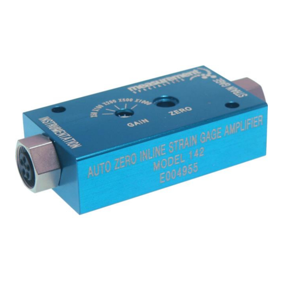
Model 142 Inline Strain Gage Amplifier
Measurement Specialties, Inc.
32 Journey, Suite 150, Aliso Viejo, CA 92656 USA
Measurement Specialties, Inc.
Vibration Sensors Design Center
32 Journey, Suite 150
Aliso Viejo, CA 92656 USA
Tel: 949-716-7324
www.meas-spec.com
vibration@meas-spec.com
www.meas-spec.com
1 of 11
TM
+1 949-716-5377
t&m@meas-spec.com
Advertisement

Related Manuals for Measurement Computing 142


Summary of Contents for Measurement Computing 142
- Page 1 Operating Manual Model 142 Inline Strain Gage Amplifier Measurement Specialties, Inc. Vibration Sensors Design Center 32 Journey, Suite 150 Aliso Viejo, CA 92656 USA Tel: 949-716-7324 www.meas-spec.com vibration@meas-spec.com Measurement Specialties, Inc. www.meas-spec.com +1 949-716-5377 32 Journey, Suite 150, Aliso Viejo, CA 92656 USA 1 of 11 t&m@meas-spec.com...
- Page 2 Operating Manual Warranty be obtained by calling Customer Service at the regional headquarters with the following Measurement Specialties, Inc. accelerometers information; model number(s), quantity, serial are warranted during a period of one year from number(s), and symptoms of the problem, if date of shipment to original purchaser to be free being returned for service.
- Page 3 Operating Manual Description The Model 142 is a remote in-line strain gage amplifier designed to be used with ¼ bridge strain gage instruments (half bridge option, see page 9). The amplifier features five user selectable gain settings with a gain accuracy of ±0.5% and offers a wide bandwidth to 100kHz. The model 142 offers a patent pending Auto-Zero function that allows the operator to zero the transducer offset voltage to within ±1.5mV.
- Page 4 Operating Manual Physical Configuration The model 142 amplifier is packaged in a compact anodized aluminum housing and includes two Binder connectors for the electrical interface. Two mounting holes are offered for the screw mounting option. The top cover of the model 142 amplifier includes the following.
- Page 5 Operating Manual Mounting Installation The model 142 in-line amplifier can be mounted with various methods. The three preferred methods of mounting are as follows: 1. Screw mounting. - The mounting surface should be flat, clean and free of any residue or foreign material.
- Page 6 Operating Manual Humidity Protection For model 142 amplifier has an ingress protection rating of IP50 (dust protection). It is not designed to be used in any wet environments. For installation in environments that could be subjected to falling water, it is recommended to install a protective shrink sleeving around the housing of the amplifier.
- Page 7 Operating Manual System Installation The model 142 amplifier is designed to be operated from 5-30Vdc excitation and provide a maximum ±2V full scale output (depending on gain setting) with a 2.5V reference voltage. The amplifier is designed to be installed in a benign environment between the strain gage instrumentation and the data acquisition system or recording instrument.
- Page 8 The leads of the completion resistor have been soldered to pads located on the top surface of the circuit board at the factory. The user can replace the resistor by first removing the cover of the 142 which is attached by four 0-80 cap screws. The user needs to follow standard industry practice in reflowing the solder attachment using a soldering iron, cleaning residual flux, and taking the proper precautions for ESD protection.
- Page 9 Operating Manual Half Bridge Strain Gage Measurements The model 142 can be wired for half bridge strain gage measurements if required. For this configuration, the completion resistor will need to be replaced with a 0Ohm value. The wiring configuration for this option is illustrated in the schematic below.
- Page 10 The derating curve is illustrated below given an ambient temperature of 70°C. For example, a 350 ohm strain gage (with matching completion resistor) cannot have an excitation voltage applied to the 142 that exceeds 25.7Vdc. There is no restriction on the pass through power (Pin 1).
- Page 11 Operating Manual Auto-Zero Function The model 142 amplifier incorporates a unique Auto-Zero feature. The Auto-Zero can be actuated by two methods. 1. Manually pushing the recessed Auto-Zero button on the top cover for a minimum of two seconds. 2. Remotely grounding the connection to Pin 5 of the Instrumentation output connector for a period of two seconds minimum.
Need help?
Do you have a question about the 142 and is the answer not in the manual?
Questions and answers