Table of Contents
Advertisement
Quick Links
Operating Manual
Precision Low-Noise DC Amplifier
Measurement Specialties, Inc.
32 Journey, Suite 150, Aliso Viejo, CA 92656 USA
Model 121
Measurement Specialties, Inc.
Vibration Sensors Design Center
32 Journey, Suite 150
Aliso Viejo, CA 92656 USA
Tel: 949-716-7324
www.meas-spec.com
vibration@meas-spec.com
www.meas-spec.com
1 of 19
TM
+1 949-716-5377
t&m@meas-spec.com
Advertisement
Table of Contents

Related Manuals for Measurement Computing 121


Summary of Contents for Measurement Computing 121
- Page 1 Operating Manual Precision Low-Noise DC Amplifier Model 121 Measurement Specialties, Inc. Vibration Sensors Design Center 32 Journey, Suite 150 Aliso Viejo, CA 92656 USA Tel: 949-716-7324 www.meas-spec.com vibration@meas-spec.com Measurement Specialties, Inc. www.meas-spec.com +1 949-716-5377 32 Journey, Suite 150, Aliso Viejo, CA 92656 USA 1 of 19 t&m@meas-spec.com...
- Page 2 Operating Manual Warranty be obtained by calling Customer Service at the regional headquarters with the following Measurement Specialties, Inc. accelerometers information; model number(s), quantity, serial are warranted during a period of one year from number(s), and symptoms of the problem, if date of shipment to original purchaser to be free being returned for service.
-
Page 3: Table Of Contents
Operating Manual Table of Contents Description 1.1 Key Features 1.2 Safety Functional Characteristics 2.1 Excitation Voltage 2.2 Sensor Sensitivity 2.3 Output Scaling 2.4 Gain 2.5 LP Filter 2.6 Auto-Zero 2.7 Shunt Calibration 2.8 Monitoring State 2.9 Fault Indication Operation 3.1 Channel Selection 3.2 Function Selection 3.3 Edit and Display Wiring Connection... -
Page 4: Description
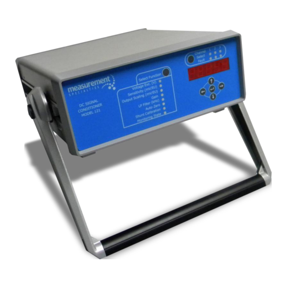
Operating Manual Description The Model 121 is a 3-Channel DC Differential Amplifier designed to be used with bridge type or differential output accelerometers, pressure transducers, and load cells. The amplifier offers an exceptionally low input noise floor of <20μVrms and wide bandwidth, out to 200 kHz, ideal for transient measurements. -
Page 5: Safety
Operating Manual Safety Read this manual in its entirety before operating the Model 121 DC Amplifier. Read all wiring and power hookup instructions and understand the requirements prior to using another manufacturer's products with the Model 121. Insure that any product being interfaced with the Model 121 is wired according to prevailing local safety and operational standards before operating. -
Page 6: Functional Characteristics
This function selection provides for programming the sensitivity of the transducer (in mV/EU). EU = Engineering Unit, such as g or m/sec^2 The Model 121 uses this information to determine the gain needed to achieve the required output scaling. The user can enter four (4) significant digits ranging from 0.001 to 1000. -
Page 7: Output Scaling
Operating Manual Output Scaling This function selection provides for programming the desired scaling of the output (in mV/EU) of the amplifier. The user can enter four significant digits ranging from 0.000 to 1000. The output scaling will be set to the desired value after the ENTER key (in the middle of the five EDIT keys) is pressed, and the gain will be set to the value determined by the following equation: Output Scaling Amplifier Gain = ---------------------------... -
Page 8: Shunt Calibration
Or, if the AC power input voltage is out of range (90~120VAC or 200~250VAC), then all of the Fault LEDs will not extinguish until the fault is corrected and the power recycled on the Model 121. The excitation voltage of all three channels will then set to 0.000V. -
Page 9: Operation
Operating Manual Operation Channel Selection Depress the “Channel Select” push-button to select the desired channel for programming. Each press of the “Channel Select” push-button will alternately illuminate one of the 3 “Channel LEDs” located to the right of the “Channel Select” push-button indicating the channel number selected for programming. -
Page 10: Edit And Display
Operating Manual Edit and Display The five EDIT keys can be used to change the setting of each function, but make sure to press the ENTER key (in the middle of the five EDIT keys) after changed the setting. If you do not press the ENTER key (in the middle of the five keys) after changed the setting, these setting will not be active. - Page 11 Operating Manual Set Sensitivity (mV/EU) Depress the “Select Function” push-button to select the “Sensitivity (mV/EU)” for programming, and then the corresponding “Function LED” will illuminate and stay illuminated until the “Select Function” push-button is pressed again to select the next function. Modifying the value of the “Sensitivity (mV/EU)”...
- Page 12 Operating Manual voltage to zero within ±100mVDC, the LED will display "FAIL". And you can press the ENTER key (in the middle of the five EDIT keys) again to start the Auto-Zero process. And you can select function to monitoring state and change the setting to DC and then press the ENTER key (in the middle of the five EDIT keys) to view the DC output voltage on the LED display.
-
Page 13: Wiring Connection
Simple Hookup for Bridge Type Sensors (Alternate Sense leads Wiring) When the cable between transducer and the 9-pin Female D-connector of the Model 121 is not too long and the power consumption of the transducer is not too much, you may choose this simple wiring... -
Page 14: Hookup For Transducers Requiring Dual Excitation
Operating Manual Hookup for Transducers Requiring Dual Excitation A differential output transducer requiring ±Dual Excitation and a common ground connection can be hooked up as follows. Note that Vexc(+) is half the voltage set by user with respect to pin 9 (virtual ground) and Vexc(-) is half the voltage below. -
Page 15: Front Panel
Operating Manual Front Panel Fault LED Channel Select Push-Button Channel LED Select Function Push-Button Five EDIT Push-Button Function LED LED Display Rear Panel Power ON/OFF Switch Output BNC Fuse Installation Socket Connector AC Power Input Transducer Connector Measurement Specialties, Inc. www.meas-spec.com +1 949-716-5377 32 Journey, Suite 150, Aliso Viejo, CA 92656 USA... -
Page 16: Input And Output Impedances
Operating Manual Input and Output Impedances Input:1MegaOhm minimum Output: 10 Ohm typical Excitation Output Limits Current: 30 mA maximum, short circuit protected Power Requirement 90~120 or 200~250 VAC 50/60 Hz, which adjusts automatically Locations of Filter Modules Installed Filter Module CH3 Installed Filter Module CH2 Installed Filter... -
Page 17: Specification
Operating Manual Specifications Measurement Specialties, Inc. www.meas-spec.com +1 949-716-5377 32 Journey, Suite 150, Aliso Viejo, CA 92656 USA 17 of 19 t&m@meas-spec.com... -
Page 18: Dimensions
Operating Manual Dimensions Dimensions shown in inches [millimeters]. INTERPRET GEOMETRIC TOLERANCING PER ANSI Y14.5M-1994. Measurement Specialties, Inc. www.meas-spec.com +1 949-716-5377 32 Journey, Suite 150, Aliso Viejo, CA 92656 USA 18 of 19 t&m@meas-spec.com... -
Page 19: Calibration And Repair
Model 121 must be specified in the following manner: 121-X If X = U, the Model 121 is supplied with NEMA 5-15 USA 3 pin Plug (120V, 60Hz) If X = E, the Model 121 is supplied with CEE 7/16 Europlug (220V, 50Hz) If X = A, the Model 121 is supplied with AS-3112 China, Australasia (220V, 50HZ) Measurement Specialties, Inc.
Need help?
Do you have a question about the 121 and is the answer not in the manual?
Questions and answers