Advertisement
Quick Links
SLEIPNER GROUP
P.O. Box 519
N-1612 Fredrikstad
Norway
www.sleipnergroup.com
To download your language go to www.sleipnergroup.com
User Manual
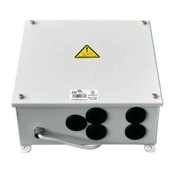
Series/parallel switch box 10112A
For Powering 24V Thruster in 12V boat
(For 99 models or newer thrusters with 4 lead electric system)
DOCUMENT ID:
5079
REVISION:
2
DATE:
2023
EN
LANGUAGE:
Advertisement

Related Manuals for Sleipner 10112A Series


Summary of Contents for Sleipner 10112A Series
- Page 1 User Manual Series/parallel switch box 10112A For Powering 24V Thruster in 12V boat (For 99 models or newer thrusters with 4 lead electric system) DOCUMENT ID: SLEIPNER GROUP 5079 REVISION: P.O. Box 519 DATE: N-1612 Fredrikstad 2023 Norway LANGUAGE: www.sleipnergroup.com...
-
Page 2: Important Notice
Introduction and planning for the installation of the Sleipner series / parallel switch box. The Sleipner series/parallel switch box have been designed to provide a safe and reliable 24V power for a 24V thruster in a 12V boat. It has been specially designed and built to accommodate for the high current demands of an electric thruster and are available in two versions, one for the SE170TC and one for the SP240TC. - Page 3 FIG 1 By this, the extra battery (Batt.2) becomes a full part of SI DE- PO W ER Sleipner the Batt.1 bank and thereby also increase the capacity of this. The box is built so that you can draw the same amount 24 VDC current from the extra Batt.2 as the thruster draws as the...
-
Page 4: Installation
Installation Install the thruster as per the installation instructions following it but disregard the wiring diagram which are being replaced by the dia- grams in this manual. Make sure to use the correct main cable size according to the length to thruster as listed in the thruster’s manual. NOTE! The length measurements in this list is the total of the + and - cable. - Page 5 FIG 3 Series / parallel switch box (IM/UM) 5079 2023...
-
Page 6: Technical Wiring Diagram
Technical wiring diagram Technical wiring diagram FIG 4 FIG 4 Series / parallel switch box installation manual Series / parallel switch box (IM/UM) 1.0.1 - 2018 5079 2023... - Page 7 Connection on the thrusters solenoids FIG 5 Existing Existing Existing Existing GREY BLUE New BLACK New GREY from from ser/par box ser/par box Example diagram if bow + stern thruster FIG 6 Battery bank 2 "Stern" 12V min. 600/800 CCA Battery bank 2 "Stern"...
- Page 8 © Sleipner Group, All rights reserved The information given in the document was right at the time it was published. However, Sleipner Group cannot accept liability for any inaccuracies or omissions it may contain. Continuous product improvement may change the product specifi cations without notice.
Need help?
Do you have a question about the 10112A Series and is the answer not in the manual?
Questions and answers