
Related Manuals for Sleipner SM901970


Summary of Contents for Sleipner SM901970
- Page 1 Installation Guide For Automatic Main Switch 897612, 897624 DOCUMENT ID: SLEIPNER AS 5196 REVISION: P.O. Box 519 DATE: N-1612 Fredrikstad 2021 Norway LANGUAGE: www.sleipnergroup.com...
-
Page 2: Table Of Contents
Contents Installation Instructions Products Considerations and Precautions..........3 Measurements ................. 4 SM901970 | 897612 - Auto-Mainswitch 12V SM901971 | 897624 - Auto-Mainswitch 24V Specifications ................5 AMS installation ................. 6 Electrical Specifications ............7 Wiring Diagram ..............8 - 10 Service .................. -
Page 3: Considerations And Precautions
• Install the automatic main switch as close to the battery(ies) as possible. • Do not connect the Sleipner automatic main switch with other products than appropriate original Sidepower control panels or other Sidepower control devices. (NB: Sleipner products are specifi cally designed with a separate fi fth control cable for the automatic main switch.) •... -
Page 4: Measurements
Thruster Measurements MC_0274 Measurement Measurement description code inch Height 194.3 Length Width 3.11 Width including fasteners 3.54 Attachment hole from the top 51.5 2.03 Attachment hole from the bottom 92.8 3.65 Attachment hole from the side 37.5 Distance between attachment hole 121.8 Attachment hole from the side 45.7... -
Page 5: Specifications
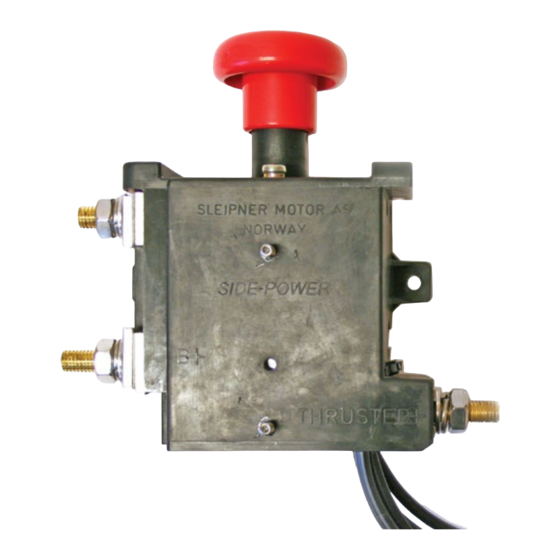
Automatic Main Switch Manual over ride button. Push to shut OFF Pull to activate ON Fuse holder Main cable(s) to the thruster Main cable(s) from battery(ies) MG_0327 5196 2021... -
Page 6: Ams Installation
AMS Installation MC_0275 ! Please refer to the graphic for special considerations relating to your model ! Installing the fuse and battery cables. Remove the nuts and all the washers. Install the fuse on top of the pre-fi tted conductors and washer. Assemble the washers, battery cables and end washer and nuts. -
Page 7: Electrical Specifications
Electrical Installation MC_0276 ! Please refer to the graphic for special considerations relating to your model ! ON/ OFF confi guration Use a 4-lead control cable between the thruster and the automatic main switch. (NB: Only 3 leads are used, The red wire is not connected into the automatic main switch.) Proportional confi... -
Page 8: Wiring Diagram
Technical Wiring Diagram Single Thruster Wiring Battery 12V or 24V Sidepower Control panel New ####-A models are ready Automatic Fuse with yellow output Main switch black yellow yellow SIDE- POWER Control 6 1225 4-lead Sidepower controlcable (only 3 used) To more control 5 lead Sidepower control cable panels... - Page 9 Technical Wiring Diagram Dual Thruster Wiring To more control stations Sidepower DUAL Control panel Yellow 8902-A or 8909-A Stern with yellow output Main positive Automatic Automatic Main switch Main switch On thruster On thruster black to positive black to positive see comments see comments SIDE-...
- Page 10 Technical Wiring Diagram Wiring with series/ parallel switch box installation IMPORTANT Do NOT use an automatic main switch between Batt 1 and Batt 2. This will prevent charging of Series/ Parallel batt.2. switch box The main switch between the batteries are only for emergencies and should be left in the ON position except in emergencies.
-
Page 11: Service
- Check the internal overheat switch (bi-metal switch on the circuit board) in the automatic main switch has not opened. (NB: It automatically resets if it is open while the main switch is cold, contact your nearest Sleipner service for assistance.) - Check 5A fuse installed on the red positive cable to the automatic main switch. -
Page 12: Spare Parts
10. This warranty gives you specific legal rights, and you may also have other rights which vary from country to country. Patents MC_0024 At Sleipner we continually reinvest to develop and offer the latest technology in marine advancements. To see the many unique designs we have patented visit our website www.sleipnergroup.com/patents 5196... - Page 13 Notes MC_0037 ..............................................................................................................................................................................................................................................................................................................................................................................................................................................................................................................................................................................................................................................................................................................................................................................................................................................................................................................................................................................................................................................................................................................................................................................................................................................................................................................................................................................................................................................................................................................................................................................................................5196 2021...
- Page 14 Notes MC_0037 ..............................................................................................................................................................................................................................................................................................................................................................................................................................................................................................................................................................................................................................................................................................................................................................................................................................................................................................................................................................................................................................................................................................................................................................................................................................................................................................................................................................................................................................................................................................................................................................................................................5196 2021...
- Page 15 Notes MC_0037 ..............................................................................................................................................................................................................................................................................................................................................................................................................................................................................................................................................................................................................................................................................................................................................................................................................................................................................................................................................................................................................................................................................................................................................................................................................................................................................................................................................................................................................................................................................................................................................................................................................5196 2021...
- Page 16 © Copyright Sleipner Motor AS, 2021 The information given in the document was correct at the time it was published. However, Sleipner Motor AS can not accept liability for any inaccuracies or omissions it may contain. Continuous product improvement may change the product specifi...
Need help?
Do you have a question about the SM901970 and is the answer not in the manual?
Questions and answers