
Related Manuals for Siel SOLEIL DSPX TLH 1500


Summary of Contents for Siel SOLEIL DSPX TLH 1500
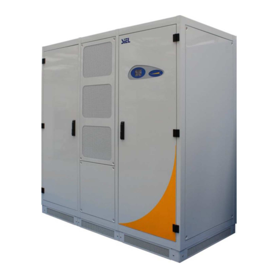
- Page 1 Inverter for photovoltaic applications INSTALLATION MANUAL SOLEIL DSPX TLH 1500 KEEP FOR FUTURE REFERENCE for the entire life of the appliance IV408E Rev.01 Installation manual Dateof issue : 2021-03-10 Pag. 1 di 26...
-
Page 2: Table Of Contents
INDICE AIM OF THE DOCUMENT ............................ 3 ................................3 VERVIEW ............................3 RAPHIC SYMBOLS USED POSITIONING..............................5 POWER CONNECTIONS AND AUXILIARIES ......................6 ............................. 6 ECHANICAL LAYOUT ..........................9 ABLE QUANTITY AND SECTION ..........................10 ROUND CONDUCTOR IZING ........................11 AXIMUM TORQUE TIGHTENING CABLES ............................ -
Page 3: Aim Of The Document
The information and technical features contained in this manual refer to the date of the drafting of the document. SIEL SPA reserves the right to modify such technical features at any moment and without warning. - Page 4 INSTALLATION INSTRUCTIONS Describe the inverter installation process step by step. MANDATORY INSTRUCTIONS Read and understand the instruction manual before working on the inverter. DISPOSAL Contains information useful for disposal of the equipment. THE WARNING TRIANGLES INDICATE INSTRUCTIONS REGARDING SAFETY FOR STAFF.
-
Page 5: Positioning
2 POSITIONING In the installation of the Soleil product, it is recommended that the distance between the inverter and any walls or other objects be respected, as shown in the following diagrams. SOLEIL DSPX xxxx TLH 1500 30cm 100cm 100cm IV408E Rev.01 Installation manual Dateof issue : 2021-03-10... -
Page 6: Power Connections And Auxiliaries
3 POWER CONNECTIONS AND AUXILIARIES 3.1 Mechanical layout The following figures illustrate the power terminals of the DC (input) and AC (output) sections. Frontal view of the inverter: Display Touch-screen User interface Air-intake grid for power modules Air-intake grid for magnetic cores Internal view of the inverter: Power core ‘A’... - Page 7 DC Terminal side: Positive pole Negative pole AC terminal side: IV408E Rev.01 Installation manual Dateof issue : 2021-03-10 Pag. 7 di 26...
- Page 8 Connecting AC side cables are dimensioned taking into account the electrical parameters of the circuit breakers, summarised in the following table: Current(A)-Curve Magnetic curve Breaking capacity [kA] 1600A 10 In (Programmable) 50kA The characteristics (curve type, magnetic current) of the switch on the electrical board connected to the inverter must be compatible with the characteristics of the machine switch.
-
Page 9: Cable Quantity And Section
3.2 Cable quantity and section The following tables indicate the maximum quantity and the maximum section of copper-made cables that can be connected to the DC input and the AC output. Inverter soleil DSPX xxxx TLH 1500 Inverter 1100M 1330M 1415M 1500M AC Cables ( cables number x section in mmq ) -
Page 10: Ground Conductor Sizing
3.3 Ground conductor Sizing The size of the ground conductor must be made according to the following table, extracted from the product Safety standard CEI EN 62109-1. The cross section of the phase conductors Relevant minimum cross section of the connected to the inverter, ‘S’... -
Page 11: Maximum Torque Tightening Cables
3.4 Maximum torque tightening cables Coppia massima di serraggio Ingresso DC Uscita AC Cavo di Terra 30 N m 3.5 FAN characteristic The following table includes the air flow volume and the power dissipation values Air capacity Air capacity Inverter Magnetics Dissipated aria [m³/h]... -
Page 12: Installation
Always visually check a UPS after delivery for any transit damage, and immediately inform Siel SPA if such damage is evident. 4.2 Unpacking The inverter packaging is usually consitituted by a plastic ground cloth, put on from the top part of the equipment and lowered till the lower limit of the equipment. - Page 13 The drive comes with plinths which close the base of the equipment. When the apparatus comes from the factory skirtings are not mounted so that it can be lifted from the bottom with a forklift. Please do not tilt or lay down the inverter on either lateral side. Following tools can be used for tran sport: - Crane Forks - Forklift...
-
Page 14: Safety Considerations
4.3 Safety considerations Accidents can be prevented by simply following a few precautions: • Walls, ceilings, floors and any other item placed next to the converter should not be made of inflammable materials. • The floor on which the inverter is installed should always be kept clean to prevent metal particles or scraps of iron or metal from being sucked inside the unit and causing short circuits. -
Page 15: Environmental Considerations
The type and the implementation of any air distribution line must be checked and approved by Siel SPA. The manufacturer is not in any way liable for inverter malfunctions due to the failure to observe the rules of Installation, particularly the permitted temperature and humidity requirements. -
Page 16: Installation Location Of Outdoor Inverters
The room intended for installation of the inverter must be a access-restricted only, such as containers, electrical substations or suitable technical rooms suited to accommodate electrical power, where no risk of items falling from above is present. The requirement of security to prevent falling objects from that area is IP3X. For indoor-type inverters, the installation site must be kept clean and dry at all times so as to prevent foreign material or liquids from entering the equipment. -
Page 17: Electrical Considerations
4.8 Electrical considerations Please refer to document IT0068 “Guidelines for the creation of photovoltaic plants” for the design recommendations for the creation of LV and MV plants based on SOLEIL DSPX inverters. 4.9 Medium to Low voltage transformer for connection to MV grid: criteria of choice. -
Page 18: Basic Installation Hints
A dedicated mounting kit provided by SIEL has to be used to secure the inverter to the metal frame. Regardless of the type of installation, the inverter has to lie on a horizontal surface, able to carry at least 1000kg/m^2. -
Page 19: Synchronization Cable And Can-Bus (Multi-Inverter Systems)
6 SYNCHRONIZATION CABLE AND CAN-BUS (MULTI-INVERTER SYSTEMS) In multi-inverter models (2200M, 2660M, 2830M, 3000M, 3300M, 4000M, 4245M, 4500M, 4400M, 5330M, 5660M, 6000M), every inverter is connected in a daisy-chain fashion with the next one and the previous one (except the Master and the last inverter of the system) as far as: •... - Page 20 SINCHRONIZATION AND CAN BUS CONNECTION EXAMPLE (DSPX 4000M TLH 1500) • Synchronization connections: black lines • CAN bus connections: white lines IV408E Rev.01 Installation manual Dateof issue : 2021-03-10 Pag. 20 di 26...
-
Page 21: Connection Of The Epo Circuit (Emergency Power Off)
7 CONNECTION OF THE EPO CIRCUIT (EMERGENCY POWER OFF) The inverter includes an electronic device (EPO) which can stop the inverter and disconnect it from the distribution network. The connection between the external EPO contact and the inverter is established by 2 wires which shall be connected to terminal 3 and 4 on the terminal board. -
Page 22: Serial Communication Connections
8 SERIAL COMMUNICATION CONNECTIONS 8.1 Type of cables to be used The inverters of the Soleil DSPX xxxx TLH 1500 series, have two RS485 serial port available as a fieldbus, with a standard Modbus RTU protocol; they also have a RS485 serial port (SAC BUS) to collect data from the parallel string boxes. - Page 23 • For SAC BUS use a shield cable with typical impedance of 120 Ohms (RS485) with four wires (nr2 for Data+ and Data- RS485 and Nr2 for the positive/negative 24Vdc power supply). Alternatively use a 120 Ohm (RS485) bipolar shielded cable for the transmission of information and a bipolar shielded cable for the 24Vdc power supply.
- Page 24 LAYOUT CONNECTION EXAMPLE MONITORUING SYSTEM - POWER PLANT CONTROLLER – PV STRING BOX IV408E Rev.01 Installation manual Dateof issue : 2021-03-10 Pag. 24 di 26...
-
Page 25: User Settings
3. Set the software feature to detect the fuse opening by means of the touch screen, as described in chapter 10 of the IV407 ‘Instruction manual SOLEIL DSPX TLH 1500’ IV408E Rev.01 Installation manual Dateof issue : 2021-03-10 Pag. -
Page 26: Control Features - Network Services
9.2 Control features – Network services Soleil and Soleil HV Inverters comply with CEI-021 regulations and with Terna attachment A70. The features regarding the ‘Network services’, summarised below, can be set by the installer through the use of the inverter touch screen operating panel, in accordance with the procedure described in the IV407 ‘Instruction manual’.
Need help?
Do you have a question about the SOLEIL DSPX TLH 1500 and is the answer not in the manual?
Questions and answers