Table of Contents
Advertisement
Available languages
Available languages
USER AND INSTALLER MANUAL
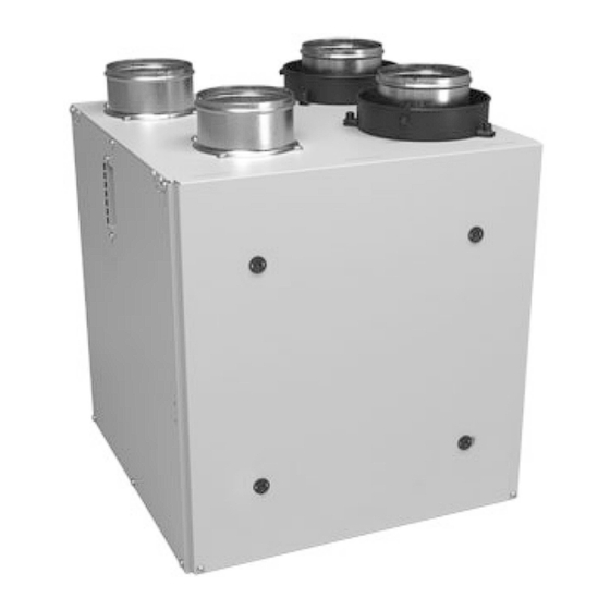
SIDE PORTS
TOP PORTS
K7 ERV
(44162)
K8 HRV
(44152)
K10 HRV
K10 HRV
(44502)
(44500)
40E
(44262)
40H+
(44252)
50H
50H
(44602)
(44600)
VB0201
VB0200
INSTALLER: READ THESE INSTRUCTIONS
SAVE THEM FOR USER
RESIDENTIAL USE ONLY
Venmar Ventilation ULC, 550 Lemire Blvd., Drummondville, Québec, Canada J2C 7W9 venmar.ca 800-567-3855
21777J
Advertisement
Chapters
Table of Contents
Troubleshooting

Related Manuals for Venmar K10 HRV


Summary of Contents for Venmar K10 HRV
- Page 1 K8 HRV (44152) K10 HRV K10 HRV (44502) (44500) (44262) 40H+ (44252) (44602) (44600) VB0201 VB0200 INSTALLER: READ THESE INSTRUCTIONS SAVE THEM FOR USER RESIDENTIAL USE ONLY Venmar Ventilation ULC, 550 Lemire Blvd., Drummondville, Québec, Canada J2C 7W9 venmar.ca 800-567-3855 21777J...
- Page 2 Please take note that this manual uses the following symbols to emphasize particular information: ⚠ WARNING Identifies an instruction which, if not followed, might cause serious personal injuries including possibility of death. CAUTION Denotes an instruction which, if not followed, may severely damage the unit and/or its components. NOTE: Indicates supplementary information needed to fully complete an instruction.
-
Page 3: Table Of Contents
6. INSTALLATION .......... 7 9.2 K8 HRV and 40H+ Units ........16 6.1 Locating the Unit ..........7 9.3 K10 HRV and 50H Units ........17 6.2 Installing the ductwork and registers ....8 10. SERVICE PARTS ........18 6.2.1 Fully ducted system ..........8 11. -
Page 4: For The User
For more information about their operation modes, refer to the Main and auxiliary wall control User Guide, VE0220 included with the ventilation unit and also available at www.vanee.ca or www.venmar.ca. Would you like to receive occasional informational e-mail off ers including Aimeriez-vous recevoir plus de détails sur nos promotions, off... -
Page 5: Maintenance
VD0243 Perform Quarterly Maintenance up to step 6, and clean the recovery core as follows: K7 ERV K8 HRV, K10 HRV*, 40H+*, 50H* Remove the dust on the core using a vacuum cleaner and a soft Soak the heat recovery core in a mixture of lukewarm water and brush attachment. -
Page 6: Warranty
For the User 4. WARRANTY This ventilation unit is a high quality product, built and packaged with care. The manufacturer warrants to the original purchaser of its product, that such products will be free from defects for the period stated below, from date of original purchase. For all units, the warranty covers parts only against any operational defect. -
Page 7: For The Installer
For the Installer 5. AIR DISTRIBUTION CAUTION Before installing this unit, please take the time to carefully read page 2 of this guide to ensure it is installed safely and and properly. ORTS NITS ORTS NITS RESH AIR TALE AIR RESH AIR TALE AIR TO BUILDING... -
Page 8: Installing The Ductwork And Registers
For the Installer 6.2 I NSTALLING THE DUCTWORK AND REGISTERS ⚠ WARNING • Never install a stale air exhaust register in a closed room where a combustion device operates, such as a gas furnace, a gas water heater or a fireplace. •... -
Page 9: Central Draw Point System - Return Side
For the Installer 6.2.3 C ENTRAL DRAW POINT SYSTEM ETURN Stale air exhaust ductwork • Same as for fully ducted system (see section 6.2.1) Fresh air distribution ductwork • Cut an opening into the furnace return duct not less than 10 feet (3.1 m) away from the furnace/air handler (A+B) •... -
Page 10: Installing Dual Exterior Hood Using Tandem
For the Installer 6.3 I NSTALLING THE XTERIOR OODS Refer to the illustration aside to connect the insulated duct to the hoods. Place a “FRESH AIR INTAKE” sticker on corresponding hood. An “Anti- 6” ø Gust Intake Hood” should be installed in regions where a lot of snow is XHAUST (152 expected to fall. -
Page 11: Connecting The Ducts To The Unit
For the Installer 6.5 C ONNECTING THE UCTS TO THE NOTE: This unit was designed to be connected to ducts of at least 4” in diameter, but can be connected to bigger sized ducts by using an appropriate transition (e.g.: 4” diameter to 5” diameter transition). CAUTION Make sure the vapor barrier on the insulated ducts does not tear during installation to avoid condensation within the ducts. -
Page 12: Controls
VE0272 Use the chart below to verify compatibility with optional controls before making any connection. Main Controls Auxiliary Controls • Altitude • Simple Touch Constructo K7 ERV, K8 HRV, K10 HRV • Deco-Touch • Constructo • 20/40/60-minute push-button timer •... -
Page 13: Constructo Or Bronze
For the Installer 7.1.3 L 7.1.4 C OUCH ONSTRUCTO IMPLE OUCH ONSTRUCTO ONSTRUCTO OR RONZE OUCH RONZE OR IMPLE OUCH RONZE NO C NC I OC OL Y R G B 5°C 41°F OFF MIN MAX -5°C 23°F -20°C -4°F NO C NC I OC OL Y R G B VE0328A VE0323... -
Page 14: Electrical Connection To The Furnace
For the Installer 7.3 E LECTRICAL ONNECTION TO THE URNACE ⚠ WARNING Never connect a 120-volt AC circuit to the terminals of the furnace interlock (standard wiring). Only use the low voltage class 2 circuit of the furnace blower control. For a furnace connected to a cooling system: On some older thermostats, energizing the “R”... -
Page 15: Wiring Diagrams
For the Installer 9. WIRING DIAGRAMS 9.1 K7 ERV 40E U NITS WARNING • Risk of electric shocks. Before performing any maintenance or servicing, always disconnect the unit from its power source. • This product is equipped with an overload protection (fuse). A blown fuse indicates an overload or a short-circuit situation. -
Page 16: K8 Hrv And 40H+ Units
For the Installer 9.2 K8 HRV 40H+ U NITS WARNING • Risk of electric shocks. Before performing any maintenance or servicing, always disconnect the unit from its power source. • This product is equipped with an overload protection (fuse). A blown fuse indicates an overload or a short-circuit situation. -
Page 17: K10 Hrv And 50H Units
For the Installer 9.3 K10 HRV 50H U NITS WARNING • Risk of electric shocks. Before performing any maintenance or servicing, always disconnect the unit from its power source. • This product is equipped with an overload protection (fuse). A blown fuse indicates an overload or a short-circuit situation. -
Page 18: Service Parts
For the Installer 10. SERVICE PARTS EPLACEMENT PARTS AND REPAIR In order to ensure your ventilation unit remains in good working condition, you must use the manufacturer genuine replacement parts only. The manufacturer replacement parts are specially designed for each unit and are manufactured to comply with all the applicable certification standards and maintain a high standard of safety. -
Page 19: Troubleshooting
For the Installer 11. TROUBLESHOOTING WARNING Risk of electric shocks. Electronic board connections must be checked by qualified personnel only. Please start any troubleshooting by resetting the unit. To do so, unplug the unit, wait one minute, and plug it back. If the issue persists, refer to the table below. - Page 20 For the Installer Integrated control Integrated control Unit does not work LED is AMBER and LED is OFF. flashing. • Unplug auxiliary controls • Uplug unit Is the power outlet Have an electrician • Wait 1 minute energized? fix it. •...
- Page 21 K10 HRV K10 HRV (44502) (44500) (44262) 40H+ (44252) (44602) (44600) VB0201 VB0200 INSTALLATEUR : LIRE ET REMETTRE CES DIRECTIVES À L’UTILISATEUR POUR USAGE RÉSIDENTIEL SEULEMENT Venmar Ventilation ULC, 550 boul. Lemire, Drummondville, Québec, Canada J2C 7W9 venmar.ca 800 567-3855 21777J...
- Page 22 Veuillez noter que dans ce guide, les symboles suivants sont utilisés afin d’accentuer certaines informations particulières : ⚠ AVERTISSEMENT Identifie une directive qui, si elle n’est pas suivie, peut causer de graves blessures corporelles ou la mort. ATTENTION Identifie une directive qui, si elle n’est pas suivie, peut gravement endommager l’appareil ou ses pièces. NOTE : Indique une information supplémentaire afin de réaliser complètement une directive.
- Page 23 9.1 K7 ERV et 40E ...........15 5. DISTRIBUTION DE L’AIR ......7 9.2 K8 HRV et 40H+ ..........16 6. INSTALLATION .......... 7 9.3 K10 HRV et 50H ..........17 10. PIÈCES DE SERVICE ......18 6.1 Emplacement de l’appareil ........7 11. DÉPANNAGE .......... 19 6.2 Installation des conduits et des grilles ....8...
-
Page 24: Pour L'utilisateur
ARRÊT au moyen du bouton-poussoir intégré. Pour de plus amples renseignements au sujet des commandes murales optionnelles, consulter le Guide de l’utilisateur, Commandes murales principales et auxiliaires inclus avec cet appareil et accessible sur www.venmar.ca et www.vanee.ca. Would you like to receive occasional informational e-mail off ers including Aimeriez-vous recevoir plus de détails sur nos promotions, off... -
Page 25: Entretien
VD0243 Effectuer l’entretien annuel jusqu’à l’étape 6, puis nettoyer le noyau comme suit: K7 ERV K8 HRV, K10 HRV*, 40H+*, 50H* Enlever la poussière sur le noyau à l’aide d’un aspirateur muni Laisser le noyau de récupération de chaleur tremper dans l’eau tiède d’une brosse à... -
Page 26: Garantie
Pour l’utilisateur 4. GARANTIE Votre appareil de ventilation est un produit de grande qualité, fabriqué et emballé avec soin. Le fabricant garantit au consommateur, acheteur initial de ses produits, que ceux-ci sont exempts de tout défaut de fabrication pour la période citée plus bas et ce, à partir de la date d’achat originale. -
Page 27: Pour L'installateur
Pour l’installateur 5. DISTRIBUTION DE L’AIR ATTENTION Avant d’installer cet appareil, prendre le temps de lire attentivement la page 2 de ce guide pour s’assurer que l’appareil est installé de façon sécuritaire et optimale. PPAREILS AVEC BOUCHES SUR LE DESSUS PPAREILS AVEC BOUCHES LATÉRALES É... -
Page 28: Installation Des Conduits Et Des Grilles
Pour l’installateur 6.2 I NSTALLATION DES CONDUITS ET DES GRILLES ⚠ AVERTISSEMENT • Ne jamais installer une grille d’évacuation d’air vicié dans une pièce où se trouve un appareil de combustion, tel qu’une fournaise, un chauffe-eau à gaz ou un foyer. •... -
Page 29: Distribution À La Source - Côté Retour
Pour l’installateur 6.2.3 D ISTRIBUTION À LA SOURCE ÔTÉ RETOUR Évacuation d’air vicié • Comme pour l’installation indépendante (section 6.2.1) Distribution d’air frais • Couper une ouverture dans le conduit de retour de la fournaise, à au moins 10 pieds (3,1 m) de celle-ci (A+B). •... -
Page 30: Installer Les Bouches Extérieures
Pour l’installateur 6.3 I NSTALLER LES BOUCHES EXTÉRIEURES Consulter l’illustration ci-contre pour relier les conduits isolés aux bouches extérieures. Une bouche « anti-rafale » pour l’aspiration d’air frais devrait ORTIE être installée dans les régions où il tombe généralement beaucoup de neige. Ø... -
Page 31: Raccordement Des Conduits À L'appareil
Pour l’installateur 6.5 R ’ ACCORDEMENT DES CONDUITS À L APPAREIL NOTE : Cet appareil a été conçu pour être raccordé à des conduits de 4 pouces de diamètre, mais peut être raccordé à des conduits de diamètre plus grand au moyen d’une transition appropriée. ATTENTION S’assurer que le coupe-vapeur ne se déchire pas durant l’installation pour éviter que ne se forme de la condensation dans les conduits. -
Page 32: Commandes
VE0272 Avant de procéder au branchement des commandes optionnelles, en vérifier la compatibilité : Commandes principales Commandes optionnelles • Altitude • Simple Touch Constructo K7 ERV, K8 HRV, K10 HRV • Deco-Touch • Constructo • Bouton-poussoir 20/40/60 minutes • Lite-Touch Constructo •... -
Page 33: Constructo Ou Bronze
Pour l’installateur 7.1.3 L 7.1.4 C OUCH ONSTRUCTO IMPLE OUCH ONSTRUCTO ONSTRUCTO OU RONZE OUCH RONZE OU IMPLE OUCH RONZE NO C NC I OC OL Y R G B 5°C 41°F OFF MIN MAX -5°C 23°F -20°C -4°F NO C NC I OC OL Y R G B VE0328F VE0323 7.1.5 C... -
Page 34: Équilibrage De L'appareil
Pour l’installateur 7.3 R ACCORDEMENT ÉLECTRIQUE À LA FOURNAISE ⚠ AVERTISSEMENT Ne jamais brancher un circuit 120 volts ca aux bornes du câblage de la fournaise (méthode standard). Utiliser seulement le circuit classe 2 du ventilateur de la fournaise. Pour une fournaise raccordée au système de climatisation : Sur certains vieux thermostats, la mise sous tension des bornes «... -
Page 35: Schémas Électriques
Pour l’installateur 9. SCHÉMAS ÉLECTRIQUES 9.1 K7 ERV ⚠ AVERTISSEMENT • Danger d’électrocution. Toujours débrancher l’appareil avant d’effectuer les travaux d’entretien ou de réparation. • Cet appareil est muni d’une protection contre les surcharges (fusible). Un fusible grillé indique une surcharge ou un court-circuit. -
Page 36: K8 Hrv Et 40H
Pour l’installateur 9.2 K8 HRV 40H+ ⚠ AVERTISSEMENT • Danger d’électrocution. Toujours débrancher l’appareil avant d’effectuer les travaux d’entretien ou de réparation. • Cet appareil est muni d’une protection contre les surcharges (fusible). Un fusible grillé indique une surcharge ou un court-circuit. -
Page 37: K10 Hrv Et 50H
Pour l’installateur K10 HRV ⚠ AVERTISSEMENT • Danger d’électrocution. Toujours débrancher l’appareil avant d’effectuer les travaux d’entretien ou de réparation. • Cet appareil est muni d’une protection contre les surcharges (fusible). Un fusible grillé indique une surcharge ou un court-circuit. Si le fusible grille, débrancher l’appareil de la prise de courant. Cesser d’utiliser l’appareil et communiquer avec le soutien technique. -
Page 38: Pièces De Service
Pour l’installateur 10. PIÈCES DE SERVICE IÈCES DE REMPLACEMENT ET SERVICE Pour assurer le bon fonctionnement de votre appareil, vous devez toujours utiliser des pièces d’origine provenant du manufacturier. Les pièces d’origine du manufacturier sont spécialement conçues pour satisfaire toutes les normes de certification de sécurité applicables. Leur remplacement par des pièces ne provenant pas du manufacturier pourrait ne pas assurer la sécurité... -
Page 39: Dépannage
Pour l’installateur 11. DÉPANNAGE ⚠ AVERTISSEMENT Danger d’électrocution. Les connexions de la carte électronique ne doivent être vérifiées que par du personnel qualifié. Si l’appareil ne fonctionne pas correctement, effectuer une réinitialisation en le débranchant pour une minute puis en le rebranchant. Si l’appareil ne fonctionne toujours pas correctement, consulter le tableau ci-dessous. - Page 40 Pour l’installateur La DEL de la L’appareil ne La DEL de la commande intégrée est commande intégrée fonc onne pas AMBRE et elle clignote. est ÉTEINTE. • Débrancher les commandes murales • Débrancher l’appareil La prise murale Consulter un • A endre 1 minute fonc onne-t-elle? électricien.
Need help?
Do you have a question about the K10 HRV and is the answer not in the manual?
Questions and answers