Advertisement
Quick Links
WARNINGS AND CAUTIONS:
• TO AVOID FIRE, SHOCK, OR DEATH: TURN OFF POWER AT CIRCUIT BREAKER OR
FUSE AND TEST THAT POWER IS OFF BEFORE WIRING!
• To be installed and/or used in accordance with appropriate electrical codes and
regulations.
• If you are unsure about any part of these instructions, consult an electrician.
Tools needed to install your Sensor
Slotted/Phillips Screwdriver
Pliers
Cutters
Parts Included List
Sensor Base (1)
#8-32 x 3/4" Screw (2)
#6-32 x 13/16" Screw (2)
FEATURES
• Adapts OSCxx Sensors to line-voltage
• 24VDC Output
• Mounts inside a 2.125" deep octagon or 4" square
Electrical Box (w/mud ring).
DESCRIPTION
The OPB15 adapts Leviton low-voltage ceiling occupancy
sensors to operate on line-voltage electrical systems.
Designed to control up to 15 amps of lighting load from
a single occupancy sensor. The Power Base contains
a power supply and a load switching relay. The power
supply provides Class 2 low-voltage power for OSCxx
Series Occupancy Sensors. The relay in the Power Base
is controlled by the occupancy sensors connected via the
control input of the two-part terminal connector. The Power
Base includes zero cross switching circuitry to minimize
inrush current associated with electronic ballasts. This
reduces wear and tear on the relay contacts making the
power pack last longer.
Application Notes:
OPB15 works well where installation of a low-voltage
wiring typical with traditional power packs and sensors
is difficult, inconvenient or costly. It is ideal for existing
buildings where access to wiring is limited or for new
construction with line-voltage circuiting only.
LOW-VOLTAGE CURRENT CAPACITY
OPB15 is designed for a single occupancy sensor with
a maximum current capacity of 40mA.
INSTALLING YOUR POWER BASE
NOTE: Use check boxes
when Steps are completed.
Occupancy Sensor Power Base
Incandescent: 15 A @ 120 VAC , Fluorescent: 15 A @ 120 VAC - Ballast, 15 A @ 277 VAC - Ballast, 3/4 Hp @ 120 VAC
Operating Temperature: 0°C to 40°C (32°F to 104°F) - Relative Humidity: 0% to 90% non-condensing.
For use with OSCxx Occupancy Sensors
INSTALLATION INSTRUCTIONS
Catalog No.
OPB15-0DW
• Input voltage tolerance 10%
• Output voltage tolerance 15%, Output voltage listed at
nominal.
WARNING: TO AVOID FIRE, SHOCK, OR
Step 1
DEATH; TURN OFF power at circuit breaker
or fuse and test that power is off before wiring!
Preparing and connecting wires:
Step 2
Make sure the wires from the wall box are
straight (cut if necessary). Remove insulation
from each wall box wire and Sensor Power
Base as shown:
Strip Gage
Cut
(if necessary)
(measure bare wire here)
Wiring your Sensor Power Base
Step 3
(Line Voltage):
NOTE: This application is based on the wall box
being pre-installed.
Connect wires per WIRING DIAGRAM as follows:
• Twist strands of each lead tightly together and, with
circuit conductors, push firmly into appropriate wire
connector. Screw connectors on clockwise making sure
no bare conductors show below the wire connectors.
WIRE DESIGNATIONS
Signal Name
Color
Line Voltage Wires
Line 120-277V
Black
Neutral
White
Load
Blue
Class 2 Two-Part Terminal
Common
Black
Power (+24VDC)
Red
Control (Occupancy Sensor)
Blue or Gray
All wires rated at 105° C. 600V insulation.
Class 2 wires are Teflon coated.
Cat. No. OPB15
Rated: 120-277 VAC, 50/60 Hz
CATALOG ITEMS
Power Input
Power Output
120-277VAC, 50/60Hz
24VDC, 40mA
WIRING DIAGRAM
Hot (Black)
Line
120-277 VAC
50/60 Hz
Neutral (White)
Mount power base in desired electrical
Step 4
box application:
A. To mount inside 4" octagon 2.125" deep ceiling
5/8"
electrical box, refer to Figure 1. Wire per Step 2.
(1.6 cm)
• Dress line voltage wires to provide enough clearance
in electrical box when device is installed.
• Partially thread the two #8-32 screws provided into
mounting holes of the electrical box.
• Align the power base body so that it fits between the
mounting holes of the electrical box and insert over
mounting screws.
• Turn counter clockwise until it reaches the stops.
• Tighten mounting screws firmly.
Figure 1
Ceiling Installation in a 4" Octagon 2.125" Electrical Box
4" Octagon 2.125" Deep
Electrical Box
Gauge
14 AWG
14 AWG
14 AWG
22 AWG
22 AWG
22 AWG
WARNINGS AND CAUTIONS:
• Sensors must be mounted on a vibration free surface.
• All sensors must be mounted at least 6 feet away from air vents, air handlers, and
reflective surfaces (windows/mirrors).
• Disconnect power when servicing fixture or changing lamps.
• Use this device with copper or copper clad wire only.
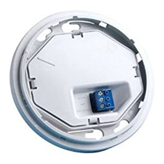
Sensor Power Base
Blue
Black
White
Step 4 cont'd
B. To mount inside 2.25"x 4"x 4" electrical box with
mud-ring, refer to Figure 2. Wire per Step 2.
• Ensure that conduit/cable entry clamp is located in
corner of electrical box.
• Dress line voltage wires to provide enough
clearance in electrical box when device is installed.
• Install a two-gang mud ring (not included) on
electrical box.
• Partially thread the two #6-32 screws provided into
the two-gang mud ring, one on the upper left and
one on the lower right, refer to Figure 2.
• Align the Power Base body so that it fits between
the mounting holes of the electrical box and insert
over mounting screws.
• Turn counter clockwise until it reaches the stops.
• Tighten mounting screws firmly.
8-32 Screws
Sensor Power Base
Two-Part Terminal
Connector
Ceiling
Sensor
DI-000-OPB15-00B
Black
Load
White
Mount power base in desired
electrical box application:
Advertisement

Related Manuals for Leviton OPB15


Summary of Contents for Leviton OPB15
- Page 1 Sensor Power Base LOW-VOLTAGE CURRENT CAPACITY Line 120-277V Black 14 AWG Neutral White 14 AWG OPB15 is designed for a single occupancy sensor with Two-Part Terminal a maximum current capacity of 40mA. Load Blue 14 AWG Connector Class 2 Two-Part Terminal...
- Page 2 fitness for a particular purpose, is limited to five years.
Need help?
Do you have a question about the OPB15 and is the answer not in the manual?
Questions and answers