Table of Contents
Advertisement
Quick Links
Advertisement
Table of Contents

Related Manuals for Full Vision TRACKMASTER TMX428


Summary of Contents for Full Vision TRACKMASTER TMX428
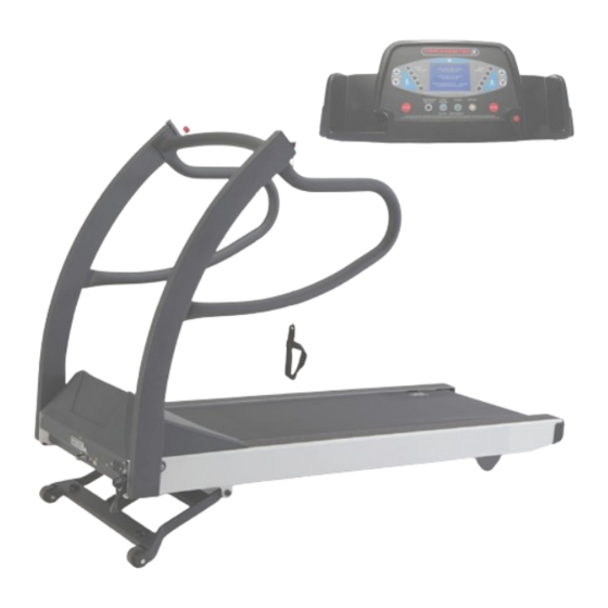
- Page 1 MEDICAL TREADMILL OWNER’S MANUAL TMX428 TMX428CP Revision Level 5 November 2018...
-
Page 3: Contact Information
électrique ou un dysfonctionnement du matériel. ® ContacterTRACKMASTER départementservicepour tous vosbesoins en piècesde rechange. ® TRACKMASTER is a registered trademark of Full Vision Inc. ® TRACKMASTER is protected by the following US Patents: 5,431,613 and 5,320,589. November 2018 TMX428 Owner’s Manual... -
Page 4: Regulatory And Safety Conformance
Safety Information TRACKMASTER Regulatory and Safety Conformance ® TRACKMASTER meets the following safety and regulatory standards for FDA Class 1 motor operated ® physical medicine machines. TRACKMASTER has been tested by Intertek Testing Services N.A Inc., and is listed by Engineering Testing Laboratories (ETL).However, the ultimate conformance to IEC 60601-1is the responsibility of the system integrator when combined with other equipment. -
Page 5: Important Safety Information
TRACKMASTER Safety Information Important Safety Information The purchaser is solely responsible for the training, instruction, supervision and safety of all ® users of the TRACKMASTER treadmill, and to use it as intended by the manufacturer. This device is intended to be used as a motion appliance to facilitate cardiac or VO medical evaluation. - Page 6 Safety Information TRACKMASTER • Walk in the center of the running belt. Contact with the side rail and the moving belt could cause injury. • The Patient must always wear the StopTether lanyard wrist strap before operating ® the TRACKMASTER •...
- Page 7 TRACKMASTER Safety Information Serious injury or death could result from electrical shock. To reduce the possibility of electrical shock, carefully observe the following precautions. • To disconnect the treadmill, set the power switch to the OFF position, and remove the plug from the outlet. When the power is off, the green light on the power switch is dark.
- Page 8 Safety Information TRACKMASTER Information Importante de Sécurité L’acheteur est entièrement responsable de l’utilisation, de la vigilance et de la sécurité des ® utilisateurs du tapis roulant TRACKMASTER telle qu’elles ont été prévues par le fabricant. Cet appareil est destiné à être utilisé pour réaliser des entraînements physiques et faciliter l’évaluation des capacités cardiaques ou de VO (Volume maximal d’oxygène).
- Page 9 TRACKMASTER Safety Information • N'essayez jamais de retirertoutarticle d'habillementtandisquele tapis roulantest en mouvement. • Toutes les personnessur et autour dutapisroulantdoiventporterclos,chaussures de protection.Lacetsdoivent être serrés etne pende pasàprovoqueruneexcursionouprendredes risques. Sandales, tongs, pantouflesetautresne sont pasconsidéréscommeclos,chaussures de protection. • Promenade dans lecentre de labande de course. Contact avec le raillatéral et letapisroulantpeutprovoquer des blessures.
- Page 10 Safety Information TRACKMASTER Des blessures gravesou même de mortpar électrocution. Pour réduire les risquesdechocélectrique, respectezles précautions suivantes. • Pour débrancher letapis roulant, placez le commutateur d'alimentation sur lapositionOFFet retirez lafiche de la prise. Lorsquel'appareil est éteint, le feu vertsurl'interrupteur d'alimentationest sombre. •...
-
Page 11: Table Of Contents
TRACKMASTER Content Contact Information ............i Regulatory and Safety Conformance . - Page 12 TRACKMASTER Safe Handling Guidelines ..........5-1 Initial Setup .
- Page 13 TRACKMASTER Control Console Will Not Illuminated ........9-1 Facility Circuit Breaker Trips When Powering Up .
-
Page 15: Chapter 1 Introduction
TRACKMASTER Introduction Introduction ® Congratulations on the purchase of your new TRACKMASTER treadmill. These fine machines have been in production since 1977 and represent state-of-the-art design for heavy- ® duty institutional use. The TRACKMASTER treadmill has gained worldwide recognition as one of the best and most dependable treadmills on the market. - Page 16 Introduction TRACKMASTER Do not use silicone sprays to wax your treadmill deck. Using silicone sprays may void the warranty. Such sprays can bring about surface changes that may cause you to slip. Attention Les avis d’Attention vous informent des dangers potentiels qui risquent d’entraîner des dommages à...
-
Page 17: Serial Decal Information
TRACKMASTER Introduction Serial Decal Information This information must be supplied when contacting the factory for parts or service. Item Name Description Manufacturer Full-Vision Inc. Model Number Identifies model of treadmill Part Number Manufacturers part number Voltage Specifies operating voltage of treadmill Hertz Specifies the electrical hertz of treadmill Amps... -
Page 18: Equipment Symbols
Introduction TRACKMASTER Equipment Symbols The following symbols appear on the equipment. Symboles de l'équipement Les symboles suivants apparaissent sur l'équipement Reading of the Owner’s Manual is mandatory. Lecturedumanuel du propriétaireest obligatoire Elevation incline / decline adjustment. Altitudeajustement de pente/recul. adjustment. Running belt speed Exécution deréglage de la vitessede courroie. - Page 19 TRACKMASTER Introduction Table 1: Guidance and Manufacturer’s Declaration – Emissions The TMX428 Series is intended for use in the electromagnetic environment specified below. The customer or user of the TMX428 Series should ensure that it is used in such an environment. Emissions Test Compliance Electromagnetic Environment –...
- Page 20 Introduction TRACKMASTER Table 4 – Guidance and Manufacturer’s Declaration – Immunity ME Equipment and ME Systems that is NOT Life-supporting The TMX428 Series is intended for use in the electromagnetic environment specified below. The customer or user of the TMX428 Series should ensure that it is used in such an environment. Immunity Test IEC 60601 Test Level Compliance...
-
Page 21: Chapter 2 Specifications
TRACKMASTER Specifications Specifications Directional Orientation References to left, right, front, and rear are based on the assumption that you are standing on the treadmill, facing the control console. All parts listed below are considered Patient Applied Parts except where noted. Patient Grab Rails Emergency Stop Button... -
Page 22: Treadmill
Specifications TRACKMASTER Treadmill • Patient weight capacity 500 lb., 227 kg • All steel construction with baked powder-coat finish • Treadmill net weight: 425 lb., 193 kg Drive System • Heavy-duty 6-peak hp. brushless, DC servo motor • 110-120VAC, 1-phase, 60 Hz, 20-amp power supply (standard) •... -
Page 23: Power Requirements
TRACKMASTER Power Requirements Power Requirements ® The TRACKMASTER is designed to operate on a dedicated 110-120 VAC 20-amp power supply or optional 220/240 VAC 15-amp. Make sure that the treadmill is connected to an outlet that looks like the following illustration. This product is equipped with a three-wire grounding-type plug. - Page 24 Power Requirements TRACKMASTER Spécifications électriques ® LeTRACKMASTER est conçu pour fonctionnersur un110-120VACalimentationde 20 ampèresdédié ou15 ampères220/240VACen option.Assurez-vousquele tapis roulant estbranché sur une prisequi ressemble àl'illustration suivante. Ce produitest équipé d'uneprise de terreà trois fils. La fichene peut être inséréedans une prisedeterre.Ce dispositif de sécuriténe doit pas êtredésactivé.Contactez un électricien qualifiésivousne parvenez pas àinsérer la fichedans la prise,ouincertainesilasortierépond aux codesélectriqueslocaux.PrisespolariséescommeNEMA...
-
Page 25: Hi Pot Test Instructions
TRACKMASTER Hi-Pot Test Hi Pot Test Instructions This test must only be performed by a qualified electrician. ® Your Trackmaster Treadmill has been Hi-Pot tested at the factory just prior to shipment and found to be within specifications. However, some facilities require Hi Pot test verification before the treadmill is put into service. -
Page 27: Assembly And Setup
TRACKMASTER Set-up Instructions Assembly and Setup ® TRACKMASTER treadmills are shipped fully assembled and packaged in a knock down condition. They are designed to pass through a standard 36” door opening measuring at least 35½”. It will be necessary to remove the door from the jam in most cases if the door is not capable of opening fully parallel to door opening. -
Page 28: Initial Setup
Set-up Instructions TRACKMASTER Initial Setup Tools required for assembly 5/16 Allen wrench (supplied) 1. The treadmill is shipped with the handrails loose, straddling the treadmill frame. It is advised that you secure the handrails in their proper location before removing the treadmill from the base of the crate. -
Page 29: Location
TRACKMASTER Set-up Instructions 5. Connect electrical 6 pin connection to J8 and quick disconnect to BC4 and BC5 to the back of the LCD Screen console from the connectors within the handrail cross brace. 6. Attach the console to the console supports with the hardware supplied in the order shown in Figure 5-3. -
Page 30: Final Setup - Running Belt Tracking Adjustment
Set-up Instructions TRACKMASTER ® LeTRACKMASTER conformeàFCC classe Ad'avis pourles émissions électromagnétiques.Il est recommandéde ne pas placerle tapis roulantà moins de5 pis. (1.5m)à partir d'appareilsélectroniquessensiblesdansla chambre ou dansune salle adjacente. Siun problème d'interférence, déplacer le tapis roulantplus loin dudispositifsensibleoudéplacersoitappareil à autredomaine, ouconsulter spécialisteEMIdesmoyenspour protéger lachambrederayonnement électromagnétique. -
Page 31: Final Setup - Test Plug Procedure
TRACKMASTER Assembly and Setup Final Setup - Test Plug Procedure ® Each TRACKMASTER TMX428 Series treadmill includes an RS-232 test plug that enables you to test the operation of the treadmill without the ECG unit attached. The plug is located on the left side of the treadmill secured to the frame by Velcro. -
Page 32: Communication Access Location
Assembly and Setup TRACKMASTER Communication Access Location The communication ports are located at the very front of the treadmill near the center of the unit. Two ports are offered with equal communication capability. The standard “Female” RS232 port and a new USB “B” port offer connectivity diversification. You will need to install the appropriate USB driver software in order to communicate with the ®... -
Page 33: Programmable Control Instructions
TRACKMASTER Operating Instructions Programmable Control Instructions TMX428CP ® The TRACKMASTER TMX428CP Programmable Control model is a dual purpose treadmill capable of running in diagnostic mode for cardiac stress testing or aVO pulmonary evaluation. The display automatically changes from a blue, full information screen (typically found on fitness treadmills), to a black screen with minimal status data upon initiating a test program within a 3 party diagnostic computer system. -
Page 34: Stop Tether
Operating Instructions TRACKMASTER Control Panel Display: The blue display screen in the center of the console provides information on how to begin your workout and provides continuous user performance data throughout the workout session. Additionally, it serves as a user interface allowing optional input of user information when a new workout begins. - Page 35 TRACKMASTER Operating Instructions Start button: The green start button is used to begin a workout session. When a new user steps onto the machine and the start up information is displayed on the screen, pressing the start button will immediately begin a 3 second countdown of the belt start at minimum belt speed. When a user has previously selected a pre-programmed workout, pressing the start button will start the first phase of the program.
-
Page 36: Workout Graphics
Operating Instructions TRACKMASTER WORKOUT GRAPHICS 1. The entire workout is represented in the form of a colored bar graph which depicts increasing workout intensity as well as workout progression and current treadmill settings. These values can be displayed in either Metric or English measurements. 2. - Page 37 TRACKMASTER Operating Instructions Press the + or – button until the desired weight appears on the screen. Press the ENTER button to continue. Press the + or – button until the correct gender appears on the screen. Press the ENTER button to continue. Press the + or –...
-
Page 38: Built-In Program Operation
Operating Instructions TRACKMASTER BUILT-IN PROGRAM OPERATION There are 10 pre-programmed workouts within the control. Select from (5) Pre- Programmed protocols and (5) interval training routines. To access these programs, complete the following steps: The following (5) Pre-Programmed Protocols are explained here. - Page 39 TRACKMASTER Operating Instructions Gerkin Protocol (Firefighter’s Test) Speed Time KPM / MPH Incline Warm-up 3 min Stage 1 1 min Stage 2 1 min Stage 3 1 min Stage 4 1 min Stage 5 1 min Stage 6 1 min Stage 7 1 min Stage 8...
- Page 40 Operating Instructions TRACKMASTER Balke- Male Speed Time KPM / MPH Incline Warm-up 2 min Stage 1 1 min Stage 2 1 min Stage 3 1 min Stage 4 1 min Stage 5 1 min Stage 6 1 min Stage 7 1 min Stage 8 1 min...
-
Page 41: Pre-Programmed Fitness Workouts
TRACKMASTER Operating Instructions Pre-Programmed Fitness Workout Data 17. To access Pre-Programmed Fitness Workouts, use the + / - key to highlight the selection and press the Yellow Enter button. 18. The screen at the right shows the (5) Fitness workouts the user can choose from. Select the desired Fitness Workout by pressing the + / - button then press the Yellow Enter button to input user information or press the Green Start... - Page 42 Operating Instructions TRACKMASTER SPEED INTERVAL WORKOUT Speed Time KPH/ MPH Incline Warm-up 1.5 min Stage 1 0.5 min Stage 2 1.5 min Stage 3 0.5 min Stage 4 1.5 min Stage 5 0.5 min Stage 6 1.5 min Stage 7 0.5 min Stage 8 1.5 min...
- Page 43 TRACKMASTER Operating Instructions PEAK INTERVAL WORKOUT Speed Time KPH/ MPH Incline Warm-up 1.5 min Stage 1 0.5 min Stage 2 1.5 min Stage 3 0.5 min Stage 4 1.5 min Stage 5 0.5 min Stage 6 1.5 min Stage 7 0.5 min Stage 8 1.5 min...
-
Page 44: User Defined Programming Workouts
Operating Instructions TRACKMASTER User Defined Programming 19. To access User Defined menu, use the + / - key to highlight the selection and press the Yellow enter button. NOTE: Any of the User Defined Programs can be altered in intensity merely by pressing + / - for belt speed or incline. -
Page 45: Preventive Maintenance
TRACKMASTER Parts List with Part Numbers Preventive Maintenance ® Regular cleaning and maintenance is essential to keep your TRACKMASTER operating at its best for many years. We recommend that you record all maintenance and service in a log (as shown in Appendix A). ®... -
Page 46: Weekly Maintenance
Preventive Maintenance TRACKMASTER Weekly Maintenance • Vacuum around and under the treadmill. Clean all exposed surfaces with a vacuum cleaner. Avoid moving the TRACKMASTER® from its original position as moving it will compromise the original belt tracking setting. • Check running belt tension. •... -
Page 47: Running Belt Tracking Adjustment
TRACKMASTER Parts List with Part Numbers Running Belt Tracking Adjustment This procedure requires the following tool: ¼” Allen wrench • NOTE: Because this adjustment is not covered under your warranty, it is important that you review these instructions thoroughly before proceeding. The patented MasterTrack ®... -
Page 48: Running Belt Tension Adjustment
Preventive Maintenance TRACKMASTER Running Belt Tension Adjustment The running belt may stretch and loosen with regular use. This looseness is noticeable when the belt tends to hesitate or stick. Adjust the tension on the belt by following the procedure and referring to the illustration below. 1. - Page 49 TRACKMASTER Parts List with Part Numbers NOTE: The drive belt may stretch and loosen with regular use. This looseness may result in a flapping noise under the hood. 1. Remove the (5) #10-32 screws located on the bottom hood with ”...
-
Page 50: Exterior Care
Preventive Maintenance TRACKMASTER Exterior Care ® The powder-coat finish on your TRACKMASTER is an extremely durable finish and requires minimal care. Do not allow perspiration to build up on your treadmill. Wipe the unit daily. Elevation Screw Lubrication The Elevation Screw must be cleaned and lubricated every 6 months to maintain proper operation of the treadmill. -
Page 51: Motor Mount Assembly
TRACKMASTER Parts List with Part Numbers Parts List with Part Numbers Motor Mount Assembly NOTES: WHEN INSTALLING THE FLYWHEEL & DRIVE SPROCKET, TIGHTEN SET SCREWS ON KEY WAY FIRST, AND THEN TIGHTEN THE SECOND SET SCREW TO MOTOR SHAFT. WHEN TIGHTENING ITEMS 5 & 6, CONTINUE TIGHTENING UNTIL MOTOR CANNOT MOVE SIDE TO SIDE. -
Page 52: Circuit Board Assembly
Parts List with Part Numbers TRACKMASTER Circuit Board Assembly Item Description Part Number Qty Bracket Circuit Board 317-709-001 Board FG0495-3 Universal Power Supply 317-160-199 HN #8-32 Nylon 001-1763 Mount Inverter Isolation 317-160-040 HHWHTS #8-32 x .375 001-1744 Trim Black 3” Lg 001-102-044 Elevation Assembly APPLY MOLY BASED GREASE 2X... -
Page 53: Pull Tether Assembly
TRACKMASTER Parts List with Part Numbers Pull Tether Assembly NOTE: ATTACHED WRIST STRAP TO CLIP KILL SWITCH CLIP COMES WITH A DOUBLE KNOT. AS PART OF 317-160-226 Item Description Part Number Qty Tether Pull w/Wrist strap 317-160-229 E-Stop Kill Switch LS500 317-160-226 Cap 1.50 x 4.00 LPDE BLK Modified 317-160-230... - Page 54 Parts List with Part Numbers TRACKMASTER DC MOTOR MOUNT ASSEMBLY CIRCUIT BOARD MOUNT ASSEMBLY ALTERNATIVE RESITOR TAP 10-32 HOLE AND SAND POWDER COAT MATERIAL FOR PROPOR GROUND CONNECTION ALTERNATIVE SWITCH TMX428 Owner’s Manual November 2018...
- Page 55 TRACKMASTER Parts List with Part Numbers Motor Pan Assembly Item Description Part Number Qty Motor Pan Weldment 317-700-001 HHCS ¼-20 x 1.25 Lg Gr 2 001-1159 FW ¼” Dia (Above) 001-1439 FW ¼” Dia 1” OD Fender (Bellow) 001-2372 Motor Isolation Stem 317-160-216 Motor Isolation Spacer 317-160-217...
-
Page 56: Motor Pan Assembly Wiring
Parts List with Part Numbers TRACKMASTER Motor Pan Assembly Wiring DC DRIVE MOTOR DC MOTOR ASSEMBLY CONNECTOR PE,W,V,U DC DRIVE MOTOR FEEDBACK CONNECTOR 115V CONFIGURATION220V CONFIGURATION BLACK (110-120) BLANK BLANK BLACK (208-240) BROWN (HOT) BROWN (HOT) BLANK BLANK RESITOR OMITE DRIVE DC SERVO PC2303-012-N Motor Pan Assembly Wiring .25 GAP... - Page 57 TRACKMASTER Parts List with Part Numbers HARNESS CONNECTOR BLACK BREAKER 3 AMP HARNESS CONNECTOR BREAKER ¼ AMP DRIVE BROWN CIRCUIT BOARD ASSEMBLY CONNECTOR COLOR CONFIGURATION RED (INCLINE COMMON) DRIVE GROUND ON WHITE (AC COMMON NYLON STANDOFF FILTER CORCOM F4635 BLUE (INCLINE HOT) BROWN (AC HOT) ALTERNATIVE POWER SWITCH...
- Page 58 Parts List with Part Numbers TRACKMASTER Motor Pan Assembly Wiring Item Description Part Number Qty Screw HHWTS #8-32 x .375 Lg 001-1744 Clamp Plastic ¼” ID 317-160-227 Harness 110V DC Treadmill 317-160-261 Harness 220V DC Treadmill 317-160-262 Harness Resistor 417-160-026 Speed Sensor Hall Effect 317-160-305 Harness Speed Sensor Hall Effect...
-
Page 59: Frame Assembly
TRACKMASTER Parts List with Part Numbers Frame Assembly APPLY MOLY BASED GREASE Frame Assembly November 2018 TMX428 Owner’s Manual... - Page 60 Parts List with Part Numbers TRACKMASTER ACTUATOR INSTALLATION NOTES: PRIOR TO INSTALLATION OF BOLT, TURN ACTUATOR END CLOCKWISE UNTIL IT STOPS. NEXT TURN COUNTER CLOCKWISE 1 ½ TURN OUT PLUS ANY ADDITIONAL REVOLUTION TO ALLOW BOLT ALIGNMENT. WHEN TIGHTENING ELEVATION BOLT AND NUT, THE WASHERS MUST MOVE FREELY.
-
Page 61: Deck Assembly
TRACKMASTER Parts List with Part Numbers Deck Assembly STRETCH ADJUSTMENT MARKS 4X SEE NOTE 2 INSTALL CAMBER SEE NOTE 3 SEE NOTE 1 NOTES: ADJUSTMENT SCREWS MUST BE MATCH TIGHTENED. PROPER TENSION IS ACHIEVED WHEN BELT CAN’T SLIP ON PULLEYS WHEN IN OPERATION. - Page 62 Parts List with Part Numbers TRACKMASTER Deck Assembly Item Description Part Number Qty Frame Assembly TMX428 317-Various Belt Running with V-Guide 317-160-002 Bolt HHCS 5/16-18 x .75” Lg 001-1167 Lock Washer 5/16” Dia 001-1451 Flat Washer 5/16” Dia 001-1440 Deck Support Channel Weldment 317-379-001 Deck Isolator 1.75”...
-
Page 63: Final Assembly
TRACKMASTER Parts List with Part Numbers Final Assembly CONNECT CABLE TO ESB CONNECT CABLE TO PULL TETHER ROUTE WIRES THRU CONNECT CONTACT I&I ROUTE CENTER & LEFT HAND THRU LEFT HANDRAIL OUTSIDE CONTACT DETAIL 1 SEE DETAIL 1 Final Assembly Circuit Board Connection CONNECT PULL TETHER CABLE TO J7 &... - Page 64 Parts List with Part Numbers TRACKMASTER Final Assembly Item Description Part Number Qty Running Deck Assembly TMX428 317-Various Handrail RH TMX428 317-712-001 Handrail LH TMX428 317-713-001 Washer Nylon 317-160-086 Lock Washer 3/8” 001-1452 Screw HSHCS 3/8”-16 x 1” Lg PLTD 001-1859 Dome Plug 317-180-008...
-
Page 65: Tmx428Cp Controller Assembly
TRACKMASTER Parts List with Part Numbers TMX428CP Controller Assembly CONNECT TO J10 ON LCD SCREEN November 2018 TMX428 Owner’s Manual 8-15... - Page 66 Parts List with Part Numbers TRACKMASTER TMX428CP Controller Assembly Item Description Part Number Qty Console Plastic LCD Configuration 317-160-270 Membrane TMX428 Overlay 317-160-232 Board FG0960-0 Console 417-160-017 RHMS #6-32 3/8” Lg 001-1745 Back Plate Fitness Panel 317-731-001 Fastener ¼-20 UNC Riv-Nut 001-1686 Rubber Control Dampener 317-160-277...
-
Page 67: Chapter 9 Troubleshooting
TRACKMASTER Troubleshooting Troubleshooting Control Console Will Not Illuminate 1. This procedure requires the use of a meter that is capable of reading at least 250 VAC and measure ohms. 2. Turn treadmill main power switch to OFF. Unplug the treadmill power cable from the wall receptacle. - Page 68 Troubleshooting TRACKMASTER in the Control Console. This is the main communication cable and is critical to have the connector properly seated on the connector. 2. Make sure the Safety Lanyard clip is connected to switch. Running Belt Slips When In Use Over a period of time, the treadmill running belt will stretch and allow slippage when used by a heavy person.
- Page 69 Appendix Maintenance Log Serial #_______________________________Date Purchased_______________ Purchased From ________________________Phone_______________________ DATE HOURS SERVICE COMPLETED COST...
- Page 70 Full Vision Inc. 3017 Full Vision Drive Newton, KS. 67114 www.full-vision.com © Full Vision Inc. 2013...
Need help?
Do you have a question about the TRACKMASTER TMX428 and is the answer not in the manual?
Questions and answers